Tripp Lite APSINT2424 Owner's Manual for APSX APSINT Inverters 932752 - Page 10
AC Input/Output Connection
 |
View all Tripp Lite APSINT2424 manuals
Add to My Manuals
Save this manual to your list of manuals |
Page 10 highlights
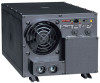
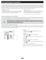
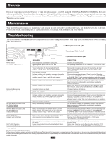
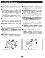
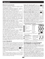
AC Input/Output Connection To avoid overloading your Inverter/Charger, be sure to match the power requirements of the equipment you plan to run at any one time (add their total watts) with the output wattage capacity of your Inverter/Charger model. When figuring the power requirements of your equipment, do not confuse "continuous" wattage with "peak" wattage ratings. Most electric motors require extra power at start-up ("peak" wattage) than required to run continuously after start-up, sometimes over 100% more. Some motors, such as in refrigerators and pumps, start and stop intermittently according to demand, requiring "peak" wattage at multiple, unpredictable times during operation. • DoubleBoost™ Feature Tripp Lite Inverter/Chargers deliver up to twice their nameplate rated wattage for up to 10 seconds,* providing the extra power needed to cold start heavy-duty tools and equipment. • OverPower™ Feature Tripp Lite Inverter/Chargers deliver up to 150% of their name plate rated wattage for up to 1 hour,* providing plenty of reserve power to reliably support tools and equipment longer. * Actual duration depends on battery age, battery charge level and ambient temperature. Connection for Models with Cords and Receptacles With a user-supplied cable and country-specific plug, connect the Inverter/Charger's IEC-320 AC Input Receptacle to your utility wall outlet. Connect your equipment directly to the Inverter/Charger's IEC-320 AC Output Receptacle(s). Select models also include a Universal AC Output Adapter which allows you to connect equipment with a wide variety of plug styles. Warning! Consult a qualified electrician and follow all applicable electrical codes and requirements for hardwire connection. Disconnect both DC input and AC utility supply before attempting hardwiring. Connection for Models with Hardwire Terminals Remove the screws and cover plate over the hardwire terminal box. Remove the knockout covers closest to the desired electrical source and to your equipment. Attach 1.28 cm diameter conduits (user-supplied) to the knockouts and thread wires through. Connect the conduits to each other with the ground bond connection supplied. OUTPUT/NEUTRAL 5 OUTPUT/HOT 4 GROUND INPUT/NEUTRAL 1 INPUT/HOT 3 "FOR USE WITH COPPER WIRE ONLY" 2 Ground* • Connect the incoming and outgoing ground wires to the ground (green) terminal 1 . AC Input • Connect the incoming hot wire to the input hot (brown) terminals 2 . • Connect the incoming neutral wire to the input neutral (blue) terminal 3 . AC Output • Connect the outgoing hot wire to the output hot (black) terminal 4 . • Connect the outgoing neutral wire to the output neutral (white) terminal 5 . • Replace cover plate and tighten screws. * If the incoming conduit only contains two wires (hot and neutral), the incoming conduit must be bonded to the main ground lug on the unit. In any case, the incoming conduit must be bonded to earth or vehicle ground, and the incoming conduit must be bonded to the outgoing conduit. 10A
-
 1
1 -
2
-
3
-
4
-
 5
5 -
 6
6 -
 7
7 -
 8
8 -
 9
9 -
 10
10 -
 11
11 -
 12
12 -
 13
13 -
 14
14 -
 15
15 -
16
-
17
-
18
-
19
-
20
-
21
-
22
-
23
-
24
-
25
-
26
-
27
-
28
-
29
-
30
-
31
-
32
-
33
-
34
-
35
-
36
-
37
-
38
-
39
-
40
-
41
-
42
-
43
-
44
 |
 |