Troy-Bilt Squall 2100 Operation Manual - Page 10
Controls & Features - engine operator s manual
 |
View all Troy-Bilt Squall 2100 manuals
Add to My Manuals
Save this manual to your list of manuals |
Page 10 highlights
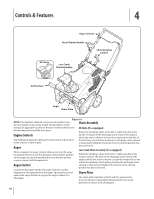
Controls & Features 4 Auger Control Recoil Starter Handle Chute Rotation Control EZ Chute Low-Crank Chute Assembly Drift Cutters Auger Shave Plate Figure 4-1 NOTE: This Operator's Manual covers several models. Snow thrower features may vary by model. Not all features in this Chute Assembly manual are applicable to all snow thrower models and the snow thrower depicted may differ from yours. EZ Chute (If so equipped) Rotate the discharge chute to the left or right using the chute Engine Controls handle. The pitch of the discharge chute controls the angle at which the snow is thrown. Loosen the wing knob on the side of See the Engine Operator's Manual for the location and function the discharge chute before pivoting the discharge chute upward of the controls on the engine. or downward. Retighten the knob once the desired position has Auger When engaged, the auger rotation draws snow into the auger housing and throws it out the discharge chute. Rubber paddles on the auger also aid in propelling the snow thrower as they come in contact with the pavement. been achieved. Low-Crank Chute Assembly (If so equipped) Rotate the discharge chute to the left or right using the chute rotation control. The pitch of the discharge chute controls the angle at which the snow is thrown. Loosen the wing knob on the side of the discharge chute before pivoting the discharge chute Auger Control upward or downward. Retighten the knob once the desired Located on the upper handle, the auger control is used to position has been achieved. engage and disengage drive to the auger. Squeeze the control Shave Plate against the upper handle to engage the auger; release it to disengage. The shave plate maintains contact with the pavement as the snow thrower is propelled, allowing snow close to the pavement's surface to be discharged. 10
-
 1
1 -
2
-
3
-
4
-
 5
5 -
 6
6 -
 7
7 -
 8
8 -
 9
9 -
 10
10 -
 11
11 -
 12
12 -
 13
13 -
 14
14 -
 15
15 -
16
-
17
-
18
-
19
-
20
-
21
-
22
-
23
-
24
-
25
-
26
-
27
-
28
-
29
-
30
-
31
-
32
-
33
-
34
-
35
-
36
-
37
-
38
-
39
-
40
 |
 |
