Troy-Bilt Squall 2100 Operation Manual - Page 7
Assembly & Set-Up - engine manual
 |
View all Troy-Bilt Squall 2100 manuals
Add to My Manuals
Save this manual to your list of manuals |
Page 7 highlights
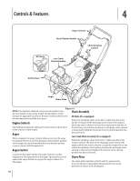
Assembly & Set-Up 3 Contents of Carton • One Snow Thrower • • One Chute Assembly • • One Snow Thrower Operator's Manual • One 20 oz. Bottle 5W-30 Oil • One Chute Rotation Control (If equip.) • One Engine Operator's Manual Two Ignition Keys One Set of Drift Cutters (If equip.) NOTE: This Operator's Manual covers several models. Snow thrower features may vary by model. Not all features in this manual are applicable to all snow thrower models and the snow thrower depicted may differ from yours. 2. Pivot the upper handle into the operating position. Be sure not to pinch any of the cables in the process. See Fig. 3-2. NOTE: All references to the left or right side of the snow thrower are from the operator's position. Any exceptions will be noted. Assembly Positioning the Upper Handle 1. Remove the wing knob and carriage bolt from the top of the lower handle. See Fig. 3-1. It is not necessary to remove the shoulder screw and flange lock nut below the wing knob and carriage bolt. Wing Knob Carriage Bolts Wing Knob Figure 3-2 Installing the Chute 1. Remove the hex washer screws in the chute base. See Fig. 3-3. Figure 3-1 Figure 3-3 7
-
 1
1 -
 2
2 -
 3
3 -
 4
4 -
 5
5 -
 6
6 -
 7
7 -
 8
8 -
 9
9 -
 10
10 -
 11
11 -
 12
12 -
13
-
14
-
15
-
16
-
17
-
18
-
19
-
20
-
21
-
22
-
23
-
24
-
25
-
26
-
27
-
28
-
29
-
30
-
31
-
32
-
33
-
34
-
35
-
36
-
37
-
38
-
39
-
40
 |
 |
