Troy-Bilt Storm 2620 Operation Manual
Troy-Bilt Storm 2620 Manual
 |
View all Troy-Bilt Storm 2620 manuals
Add to My Manuals
Save this manual to your list of manuals |
Troy-Bilt Storm 2620 manual content summary:
- Troy-Bilt Storm 2620 | Operation Manual - Page 1
Practices • Set-Up • Operation • Maintenance • Service • Troubleshooting • Warranty Operator's Manual Two-Stage Snow Thrower - Storm 2410, 2620, 2840 & 3090XP WARNING READ AND FOLLOW ALL SAFETY RULES AND INSTRUCTIONS IN THIS MANUAL BEFORE ATTEMPTING TO OPERATE THIS MACHINE. FAILURE TO COMPLY - Troy-Bilt Storm 2620 | Operation Manual - Page 2
's Owner's/Operator's Manual, packed separately with your machine, for more information. Table of Contents Safe Operation Practices 3 Assembly & Set-Up 7 Controls 13 Operation 16 Maintenance & Adjustment 17 Service 20 Troubleshooting 24 Replacement Parts 25 Attachments 26 Warranty Back - Troy-Bilt Storm 2620 | Operation Manual - Page 3
electric start engines. 4. Adjust auger housing height to clear gravel or crushed rock surfaces. 5. Disengage all control levers before starting the engine. 6. Never attempt to make any adjustments while engine is running, except where specifically recommended in the operator's manual. 7. Let engine - Troy-Bilt Storm 2620 | Operation Manual - Page 4
fuel machine indoors. 9. Exercise caution when changing direction and while d. Never remove gas cap or add fuel while the engine is operating on slopes. Do not operate on steep slopes. hot or running. 10. Plan your snow-throwing pattern to avoid discharge e. Allow engine to cool at least two - Troy-Bilt Storm 2620 | Operation Manual - Page 5
their proper operation regularly. Refer to the maintenance and adjustment sections of this manual. 2. Before cleaning, repairing, or inspecting machine disengage all control levers and stop the engine. Wait until the auger/impeller come to a complete stop. Disconnect the spark plug wire and ground - Troy-Bilt Storm 2620 | Operation Manual - Page 6
attempting to assemble and operate. Symbol Description READ THE OPERATOR'S MANUAL(S) Read, understand, and follow all instructions in the manual(s) before attempting to assemble and operate WARNING- ROTATING BLADES Keep hands out of inlet and discharge openings while machine is running. There - Troy-Bilt Storm 2620 | Operation Manual - Page 7
3 Contents of Carton • One Snow Thrower • One Snow Thrower Operator's Manual • One Engine Manual • Two Replacement Auger Shear Pins • One Chute Assembly (Model 2410) • One Product Registration Card • One Chute Control Rod (Models 2620, 2840 and 3090XP) Assembly Handle 1. Place the shift lever - Troy-Bilt Storm 2620 | Operation Manual - Page 8
to apply swift, firm pressure to the back of each. Chute Assembly and Directional Control (Models 2620, 2840 and 3090XP) 1. Remove cotter pin, wing nut and hex screw from chute control head. Remove clevis pin and bow-tie cotter pin from chute support bracket. See Fig. 3-6. Chute Control Head Chute - Troy-Bilt Storm 2620 | Operation Manual - Page 9
line up the hole in the rod with the NOTE: The chute will not rotate without squeezing the arrow on the pinion gear. See Fig. 3-11. trigger on the joystick. NOTE: The chute control rod will fit snuggly into the pinion gear. Support the rear of the dash panel with one hand Chute Control Input - Troy-Bilt Storm 2620 | Operation Manual - Page 10
The chute clean-out tool is fastened to the top of the auger housing with a mounting clip and a cable tie at the factory. Cut the cable tie before operating the snow thrower. See Fig. 3-15. cable guide on top of the engine. Some models only have one cable to route through the cable guide. See Fig - Troy-Bilt Storm 2620 | Operation Manual - Page 11
and 2620) NOTE: The upper chute on models 2840 and 3090XP is also controlled by the 4-way Chute Directional Control. See Fig. 4-1. The distance snow is thrown can be adjusted by changing the angle of the chute assembly. To do so: 1. Stop the engine. Refer to the Engine Operator's Manual. Remove the - Troy-Bilt Storm 2620 | Operation Manual - Page 12
" position, the cable should have very little slack. It should NOT be tight. 2. In a well-ventilated area, start the snow thrower engine. Refer to Engine Operator's Manual. 3. While standing in the operator's position (behind the snow thrower), engage the auger. 4. Allow the auger to remain engaged - Troy-Bilt Storm 2620 | Operation Manual - Page 13
Features 4 Chute Assembly Chute Clean Out Tool Drive Control Shift Lever † Headlight † 4-Way/2-Way Chute Directional Control † Auger Control Heated Grips † Steering Trigger Control † Standard Chute Directional Control † Augers Skid Shoe † If Equipped Figure 4-1 Snow thrower controls and - Troy-Bilt Storm 2620 | Operation Manual - Page 14
to engage the augers and start snow throwing action. Release to stop. Drive Control / Auger Clutch Lock The chute directional control is located on left side of the snow thrower. To change the direction in which snow is thrown, rotate chute directional control. 2-Way Chute Directional Control (if - Troy-Bilt Storm 2620 | Operation Manual - Page 15
snow and ice become lodged in the chute assembly during operation, proceed as follows to safely clean the chute assembly and chute opening: 1. Release both the Auger Control and the Drive Control. 2. Stop the engine. Refer to the Engine Operator's Manual. Remove the key. 3. Remove the clean-out - Troy-Bilt Storm 2620 | Operation Manual - Page 16
the auger shear pins with anything other than OEM Part No. 738-04124A replacement shear pins. Any damage to the auger gearbox or other components as a result of failing to do so will NOT be covered by your snow thrower's warranty. warning! Always turn off the snow thrower's engine and remove the - Troy-Bilt Storm 2620 | Operation Manual - Page 17
Maintenance & Adjustments 6 Maintenance Engine Refer to the Engine Operator's Manual. Shave Plate and Skid Shoes The shave plate and skid shoes on the bottom of the snow thrower are subject to wear. They should be checked periodically and replaced when necessary. NOTE: Deluxe skid shoes (on select - Troy-Bilt Storm 2620 | Operation Manual - Page 18
, remove the shear pins from the auger shaft. Spray lubricant inside the shaft and around the spacers and the flange bearings found at either end of the shaft. See Fig. 6-3. Adjustments Figure 6-3 Drive Control When the drive control is released and in the disengaged "up" position, the cable - Troy-Bilt Storm 2620 | Operation Manual - Page 19
-up section for instructions on adjusting the chute assembly. Skid Shoes Refer to the Assembly and Set-up section for instructions on adjusting the skid shoes. Chute Control Rod (Models 2620, 2840, y 3090XP) To adjust the chute control rod, proceed as follows: 1. Remove the cotter pin from the hole - Troy-Bilt Storm 2620 | Operation Manual - Page 20
snow thrower's auger belt, proceed as follows: 4. Carefully pivot the snow thrower up and forward so that it rests on the auger housing. 5. Remove the frame cover from the underside of the snow thrower by removing the self-tapping screws which secure it. See Fig. 7-3. 1. Allow the engine to run - Troy-Bilt Storm 2620 | Operation Manual - Page 21
7. Remove the belt from around the auger pulley, and slip the Drive Belt belt between the support bracket and the auger pulley. See Fig. 7-5. To remove and replace your snow thrower's drive belt, proceed as follows: 1. To prevent spillage, remove all fuel from tank by running engine until it - Troy-Bilt Storm 2620 | Operation Manual - Page 22
or phone Customer Support as instructed on page 2 for information on ordering a Service Manual. To inspect the friction wheel, proceed as follows: 1. Allow the engine to run until it is out of fuel. Do not attempt to pour fuel from the engine. 2. Carefully pivot the snow thrower up and forward - Troy-Bilt Storm 2620 | Operation Manual - Page 23
in reverse order to reassemble components. NOTE: Make sure the shift lever pin is in place in the bearing housing. See Fig. 7-9 inset. 5. After replacing the friction wheel, perform the Drive Control test on page 18 in the Maintenance and Adjustments section. Figure 7-10 Section 7 - Service 23 - Troy-Bilt Storm 2620 | Operation Manual - Page 24
Engine over-governed. 1. Carburetor not adjusted properly. 1. Loose parts or damaged auger. 1. Spark plug wire loose. 2. Gas cap vent hole plugged. 1. Move choke to CHOKE position. 2. Connect wire to spark plug. 3. Fill tank with clean, fresh gasoline. 4. Prime engine as instructed in the Operation - Troy-Bilt Storm 2620 | Operation Manual - Page 25
-tie Cotter Pin 784-5580 790-00091 Slide Shoe, Standard Slide Shoe, Deluxe 931-2643 Chute Clean-out Tool 790-00120 790-00121 790-00118 790-00119 Shave Plate (Storm 2410) Shave Plate (Storm 2620) Shave Plate (Storm 2840) Shave Plate ((Storm 3090XP) 731-05632 Key 951-10292 Spark Plug Phone - Troy-Bilt Storm 2620 | Operation Manual - Page 26
, price and availability (have your full model number and serial number ready). Model Number Description 753-05762A OEM-390-679 490-241-0010 OEM-390-995 490-241-Y014 *Not compatible with Storm 2410. Heated Grips* Drift Cutter Kit Polymer Skid Shoe Kit Snow Thrower Protective Cover Troy-Bilt Snow - Troy-Bilt Storm 2620 | Operation Manual - Page 27
Notes 11 27 - Troy-Bilt Storm 2620 | Operation Manual - Page 28
. Normal wear parts include, but are not limited to items such as: batteries, belts, blades, blade adapters, tines, grass bags, wheels, rider deck wheels, seats, snow thrower skid shoes, friction wheels, shave plates, auger spiral rubber and tires. Attachments - Troy-Bilt warrants attachments for - Troy-Bilt Storm 2620 | Operation Manual - Page 29
Máquina quitanieve de dos etapas - Storm 2410, 2620, 2840 & 3090XP ADVERTENCIA LEA Y SIGA TODAS LAS INSTRUCCIONES DE ESTE MANUAL ANTES DE PONER EN FUNCIONAMIENTO ESTA MÁQUINA. SI NO RESPETA ESTAS INSTRUCCIONES PUEDE PROVOCAR LESIONES PERSONALES. TROY-BILT LLC, P.O. BOX 361131 CLEVELAND, OHIO - Troy-Bilt Storm 2620 | Operation Manual - Page 30
opere la máquina. En caso de no hacerlo podrían producirse lesiones personales o daños materiales. Toda la información contenida en este manual Troy-Bilt se encuentran en esta página. Queremos garantizar su entera satisfacción en todo momento. En este manual y mire hacia la parte inferior de la secci - Troy-Bilt Storm 2620 | Operation Manual - Page 31
este manual. Al igual que con cualquier tipo de equipo motorizado, un descuido o error por parte del todos los felpudos, periódicos, trineos, tablas, cables y otros objetos extraños con los que podría pueden producir lesiones oculares graves. 2. No opere la máquina sin la vestimenta adecuada para - Troy-Bilt Storm 2620 | Operation Manual - Page 32
específicamente recomendados en el manual del operador. 7. Deje que cuando se las suelta. Nunca opere la máquina si falta un montaje óxido de carbono, un gas inodoro y letal. No anormal, detenga el motor, desconecte el cable de la bujía y póngala l. hasta que todas las partes móviles se hayan detenido - Troy-Bilt Storm 2620 | Operation Manual - Page 33
/ impulsor se detenga por completo. Desconecte el cable de la bujía y póngalo haciendo masa contra todos los componentes y reemplácelos sólo con partes de los fabricantes de equipos originales (OEM). ropa, etc. 11. Consulte siempre el manual del operador para obtener instrucciones adecuadas para el - Troy-Bilt Storm 2620 | Operation Manual - Page 34
en este producto. Lea el manual del operador para obtener la informaci motor contienen el monóxido de carbono, un gas inodoro y mortal. ADVERTENCIA - ELECTROCHOQUE No use el juez en la lluvia. ADVERTENCIA - SUPERFICIE CALIENTE Las partes del motor, especialmente el silenciador, llega a - Troy-Bilt Storm 2620 | Operation Manual - Page 35
Quitanieve • Un Manual del Motor • Dos pasadores de cuchilla de barrena de repuesto • Varilla hexagonal Montaje Manija 1. Coloque la palanca de cambios en la posición de avance (F) 6. 2. Observe el área inferior trasera de la máquina quitanieve para asegurarse de que ambos cables estén alineados - Troy-Bilt Storm 2620 | Operation Manual - Page 36
2. Cierre a los guardas de reborde para asegurar la asamblea Montaje del canal (Modelos 2620, 2840, y 3090XP) de tobogán a la base del tobogán. Los guardas de reborde harán clic en el lugar cuando aseguran apropiadamente. 1. Retire el pasador de chaveta, - Troy-Bilt Storm 2620 | Operation Manual - Page 37
tolva de Vista desde arriba entrada Figura 3-9 Figura 3-11 Nota: La barra hexagonal se ajusten perfectamente en el engranaje del piñón. Apoyo a la parte trasera del panel de instrumentos con una mano mientras inserta la varilla hexagonal con la otra mano para asegurar la barra hexagonal se inserta - Troy-Bilt Storm 2620 | Operation Manual - Page 38
Fig. 3-3. Herramienta de limpieza del canal 9. Controle que todos los cables estén adecuadamente dirigidos a través de la guía de cables de la parte superior del motor. Algunos modelos tienen sólo un cable para dirigir por la guía de cable. Vea la Fig. 3-13. La herramienta de limpieza del canal - Troy-Bilt Storm 2620 | Operation Manual - Page 39
é contra el suelo para evitar el desgaste desparejo de las mismas. 3. Vuelva a ajustar bien las tuercas y los pernos. Asamblea del canal (Modelos 2410 & 2620) NOTA: La asamblea del canal en los modelos 2840 y 3090XP es controlada por la 4-forma direccional del canal de control. Vea la fig. 4-1. Se - Troy-Bilt Storm 2620 | Operation Manual - Page 40
quitanieve. Consulte la sección Encendido del motor en el manual de motor. 3. Asegúrese de que el regulador se partes móviles se detengan antes de volver a ajustar el control de la barrena. 7. Para volver a ajustar el cable de control, afloje la tuerca hexagonal superior en la ménsula del cable - Troy-Bilt Storm 2620 | Operation Manual - Page 41
Controles y Características Control de Transmisión Palanca de Cambios † Montaje del Canal Herramienta de Limpieza del Canal Faro Delantero † 4 Control del Canal de Dos/Cuatro Direcciones † Control de la Barrena Agarre Termico † Control Disparador del Manejo † Control direccional del canal † - Troy-Bilt Storm 2620 | Operation Manual - Page 42
la nieve, gire la palanca de mando hacia adelante o atrás. Para activar los agarres térmicos, mueva el interruptor que se encuentra en la parte posterior del panel de instrumentos a la posición ON (conectado). Para desactivar los puños calefactables, mueva el interruptor que se encuentran en la - Troy-Bilt Storm 2620 | Operation Manual - Page 43
la nieve y el hielo que se formaron cerca del conjunto del canal. 5. Vuelva a ajustar la herramienta de limpieza al pasador de ensamblado ubicado en la parte posterior de la caja de la barrena, inserte de nuevo la llave y encienda el motor de la máquina quitanieve. Parado en la posición del operador - Troy-Bilt Storm 2620 | Operation Manual - Page 44
máquina quitanieve y retirar la llave antes de cambiar los pasadores de cuchilla. Para activar los agarres térmicos, mueva el interruptor que se encuentra en la parte posterior del panel de instrumentos a la posición ON (conectado). Vea la Fig. 5-1. Figura 5-2 Figura 5-1 44 - Troy-Bilt Storm 2620 | Operation Manual - Page 45
Mantenimiento y Ajustes 6 Mantenimiento Motor Consulte el Mantenimiento del Motor para motores embalado con la máquina para ver el mantenimiento del motor. Placa de raspado y zapatas antideslizantes La placa de raspado y las zapatas antideslizantes ubicadas en la base de la máquina quitanieve est - Troy-Bilt Storm 2620 | Operation Manual - Page 46
la transmisión. Proceda de la siguiente manera: 1. Apague el motor como se indica en el manual del motor por separado. 2. Afloje la tuerca hexagonal inferior del soporte del cable de la transmisión. Vea la Fig. 6-5. Figura 6-4 46 Sección 6- Mantenimiento y Ajustes Figura 6-5 3. Ubique la ménsula - Troy-Bilt Storm 2620 | Operation Manual - Page 47
del ajuste de las zapatas antideslizantes. Varilla de control del canal (Modelos 2620, 2840, y 3090XP) Para ajustar la varilla de control del canal resortes, los cojinetes y los cables. 5. Elimine todo el polvo del exterior del motor y del equipo. NOTA: Consulte el manual del operador del motor para - Troy-Bilt Storm 2620 | Operation Manual - Page 48
Servicio 7 Cambio de Correa Correa de la Barrena Para retirar y reemplazar la correa de la barrena de su máquina quitanieve, proceda como se indica a continuación: 1. Deje que el motor funcione hasta que se acabe el combustible. 4. Gire con cuidado la máquina quitanieve hacia arriba y hacia - Troy-Bilt Storm 2620 | Operation Manual - Page 49
7. Retire la correa de alrededor de la polea de la barrena y deslice la misma entre la ménsula de soporte y la polea de la barrena. Vea la Fig. 7-5. 3. Quite la correa como sigue: Vea la Fig. 7-6: a. Saque la correa de la barrena de la polea del motor. b. Use una llave para girar la polea loca - Troy-Bilt Storm 2620 | Operation Manual - Page 50
de parada Extracción de la Rueda de Fricción (Storm 2410, 2620 & 2840) Si la máquina quitanieve no se mueve , y si al realizar el ajuste del cable de control de la transmisión el problema la página 28 para la información sobre pedir un manual de reparaciones. Para examinar la rueda de fricción, - Troy-Bilt Storm 2620 | Operation Manual - Page 51
5. Retire con cuidado la tuerca hexagonal y la arandela que sujetan el eje hexagonal al marco de la máquina quitanieve, y golpee suavemente el extremo del eje para desplazar el cojinete de bolas del lado derecho del marco. Vea la Fig. 7-9. NOTA: Tenga cuidado de no dañar las roscas del eje. 7. Para - Troy-Bilt Storm 2620 | Operation Manual - Page 52
1. El control del cebador no está en la posición CHOKE (encendido). 2. Se ha desconectado el cable de la bujía. 3. El depósito de combustible está vac toma de corriente alterna. 1. Mueva el control del cebador a la posición RUN (apagado). 2. Llene el tanque con gasolina limpia y fresca. 3. Vacíe - Troy-Bilt Storm 2620 | Operation Manual - Page 53
3. La fricción de la rueda desgastada. 1. El montaje del canal está tapado. 2. Hay un objeto extraño en la barrena. Chute no girar 180 grados 3. El cable del control de la barrena necesita un ajuste. 4. La correa de la barrena está floja o dañada. 5. El o los pasadores de cuchilla están quebrados - Troy-Bilt Storm 2620 | Operation Manual - Page 54
-00118 790-00119 Placa de raspado (Storm 2410) Placa de raspado (Storm 2620) Placa de raspado (Storm 2840) Placa de raspado (Storm 3090XP) 731-05632 Llave 951-10292 Bujía Llame por teléfono al (800) 828-5500 para solicitar piezas de reemplazo o un Manual de Piezas de Repuesto completo (tenga - Troy-Bilt Storm 2620 | Operation Manual - Page 55
mero de serie). Número de modelo Descripción 753-05762A OEM-390-679 490-241-0010 OEM-390-995 490-241-Y014 * No es compatible con Storm 2410. Puños Calentados* Lleve Juego de Cortador Juego Zapata Antideslizante de Polímero Cubierta protectora de Máquina Quitanieve Mantenimiento Juego de Máquina - Troy-Bilt Storm 2620 | Operation Manual - Page 56
o desastre natural. El daño resultante por la instalación o el uso de piezas, accesorios o aditamentos no aprobados por Troy-Bilt para su uso con el(los) producto(s) incluido(s) en este manual anulará la garantía en lo que respecta a esos daños. Se garantiza que las Piezas con Desgaste Normal est
-
 1
1 -
 2
2 -
 3
3 -
 4
4 -
 5
5 -
 6
6 -
 7
7 -
8
-
9
-
10
-
11
-
12
-
13
-
14
-
15
-
16
-
17
-
18
-
19
-
20
-
21
-
22
-
23
-
24
-
25
-
26
-
27
-
28
-
29
-
30
-
31
-
32
-
33
-
34
-
35
-
36
-
37
-
38
-
39
-
40
-
41
-
42
-
43
-
44
-
45
-
46
-
47
-
48
-
49
-
50
-
51
-
52
-
53
-
54
-
55
-
56
 |
 |
TROY-BILT LLC, P.O. BOX 361131 CLEVELAND, OHIO 44136-0019
Printed In USA
O
PERATOR
’
S
M
ANUAL
Safe Operation Practices • Set-Up • Operation •
Maintenance • Service • Troubleshooting •
Warranty
WARNING
READ AND FOLLOW ALL SAFETY RULES AND INSTRUCTIONS IN THIS MANUAL
BEFORE ATTEMPTING TO OPERATE THIS MACHINE.
FAILURE TO COMPLY WITH THESE INSTRUCTIONS MAY RESULT IN PERSONAL INJURY.
Form No. 769-06897
(May 17, 2011)
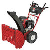
Two-Stage Snow Thrower — Storm 2410, 2620, 2840 & 3090XP