Troy-Bilt Storm 2620 Operation Manual - Page 8
Chute Directional Control Model 2410, Chute Assembly and Directional Control, Models 2620, 2840 - used
 |
View all Troy-Bilt Storm 2620 manuals
Add to My Manuals
Save this manual to your list of manuals |
Page 8 highlights
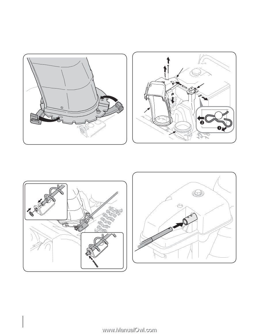
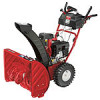
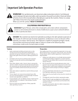
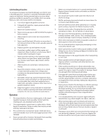
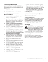
2. Close the flange keepers to secure the chute assembly to the chute base. The flange keepers will click into place when properly secure. See Fig. 3-4. NOTE: If the flange keepers will not easily click into place, use the palm of your hand to apply swift, firm pressure to the back of each. Chute Assembly and Directional Control (Models 2620, 2840 and 3090XP) 1. Remove cotter pin, wing nut and hex screw from chute control head. Remove clevis pin and bow-tie cotter pin from chute support bracket. See Fig. 3-6. Chute Control Head Chute Support Bracket Chute Chute Base Figure 3-4 Figure 3-6 Chute Directional Control (Model 2410) 2. Insert chute control rod into chute control head. Push rod as far into chute control head as possible, keeping the 1. Remove the plastic cap (if present), flat washer and hairpin holes in the rod pointing upward. See Fig. 3-7. clip from the end of the chute directional control. See Fig. 3-5. Figure 3-5 2. Insert the end of the chute directional control into the lower bracket and secure with the flat washer and hairpin clip just removed. If necessary, the lower bracket can be adjusted. Refer to Chute Bracket Adjustment on Page 19. 8 Section 3- Assembly & Set-Up Figure 3-7
-
 1
1 -
2
-
 3
3 -
 4
4 -
 5
5 -
 6
6 -
 7
7 -
 8
8 -
 9
9 -
 10
10 -
 11
11 -
 12
12 -
 13
13 -
14
-
15
-
16
-
17
-
18
-
19
-
20
-
21
-
22
-
23
-
24
-
25
-
26
-
27
-
28
-
29
-
30
-
31
-
32
-
33
-
34
-
35
-
36
-
37
-
38
-
39
-
40
-
41
-
42
-
43
-
44
-
45
-
46
-
47
-
48
-
49
-
50
-
51
-
52
-
53
-
54
-
55
-
56
 |
 |