URC MRF-200 Owners Manual
URC MRF-200 Manual
 |
View all URC MRF-200 manuals
Add to My Manuals
Save this manual to your list of manuals |
URC MRF-200 manual content summary:
- URC MRF-200 | Owners Manual - Page 1
MRF-200 INSTALLATION MANUAL Multi-Room "No-Pointing" RF Control of Audio/Video Components - URC MRF-200 | Owners Manual - Page 2
MRF-200 Installation Manual © 2003 Universal Remote Control, Inc. The information in this manual is copyright protected. No part of this manual may be copied or reproduced in any form without prior written consent from Universal Remote Control, Inc. UNIVERSAL REMOTE CONTROL, INC. SHALL NOT BE LIABLE - URC MRF-200 | Owners Manual - Page 3
OF CONTENTS Introduction 1 Features and Benefits 2 Parts Guide 2 Front Panel 3 Mounting Plate 3 Power LED 3 Status LED 3 Front Blaster 3 Rear Panel 4 Flashers 4 Power Supply 4 Bottom Panel 4 Receiver ID# 4 A Standard MRF-200 System 5 Standard Installation - Step by Step - URC MRF-200 | Owners Manual - Page 4
The combination of the MX-800 with it's companion MRF-200 base station will enable you to place your audio/video components out of sight behind closed doors and/or in another room of your house. The MX-800 sends radio signals to the MRF-200 throughout your house (50-100' away, indoors or outdoors - URC MRF-200 | Owners Manual - Page 5
them (thus allowing up to 96 identical components in one house). Parts Guide The MRF-200 RF Base Station includes: 1 - MRF-200 Receiver with integrated antenna 1 - Mounting Plate for wall mounting the MRF-200 4 - Screws for wall mounting the mounting plate 1 - 9V-300mA Power Supply 6 - Flashers - URC MRF-200 | Owners Manual - Page 6
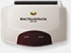
MRF-200 BASE STATION MRF-200 Details Red POWER LED lights when the MRF-200's power supply is plugged into an active AC outlet. Red STATUS LED lights when the MRF-200 receives an RF signal from the MX-800. The MRF-200's slots enable the Mounting Plate's matching guides to slide and "snap" into - URC MRF-200 | Owners Manual - Page 7
Integrated Antenna swings in any direction to optimize RF reception and range. MRF-200 BASE STATION Included 9V power supply plugs into the MRF-200's power connector. Six Rear Flasher Line Output Jacks connect flashers for control of A/V components out of sight of the MRF200's Front Blaster. Six - URC MRF-200 | Owners Manual - Page 8
add additional MRF200 receivers as needed by ordering an accessory MRF-200 base station. Do not change the factory default settings in RF Manual or the animated Tutorial. Both are available as free downloads from the www.hometheatermaster.com website. Important Note: Do NOT power up the MRF-200 - URC MRF-200 | Owners Manual - Page 9
MRF-200 BASE STATION with the enclosed screws, then the receiver is slid back into place front blaster, you will need to utilize the included Flashers plugged into the MRF-200's rear Flasher Line Output jacks. If you have problems with components that are close to the Front Blaster, see the next page - URC MRF-200 | Owners Manual - Page 10
MRF-200 BASE STATION Front Blaster Overload A few models of audio/video components can be OVERLOADED by the Front Blaster. If you are having intermittent or inconsistent results with a particular component, try repositioning the MRF-200 and facing the Front Blaster in a different direction. If this - URC MRF-200 | Owners Manual - Page 11
MRF-200 BASE STATION Controlling An Array of Identical TV's (or VCR's, Receivers, CD players etc.) There are several considerations to take into account when you are installing an MRF-200 to control an array of identical components: 1. You cannot use the Front Blaster to control identical components - URC MRF-200 | Owners Manual - Page 12
MRF-200 BASE STATION Step 3 - Copy The Programmed Device In tree view, right click on the device you programmed. From the context menu that appears, select COPY. Step 4 - Paste - URC MRF-200 | Owners Manual - Page 13
MRF-200 BASE STATION Click on the "cell" for the first identical TV, by crossing the device row with the Signals column. Signal Column TV1 Device Row Select RF - URC MRF-200 | Owners Manual - Page 14
MRF-200 BASE STATION Programming For Multiple Equipment Locations You can operate up to 16 by clicking Each LOCATION should have on the Rename button. a unique ID#. It is ok to install multiple MRF-200's in one location. Step 4 - Save and Download to your MX-800's. Page 11 Delete receivers by - URC MRF-200 | Owners Manual - Page 15
MRF-200 BASE STATION Frequently Asked Questions Can I use flasher/emitters that I have already installed in the system to connect to the MRF-200? Yes, the flashers are compatible, however flashers from other companies are equipped with a mini plug that is too large to fit the MRF-200's flasher jacks - URC MRF-200 | Owners Manual - Page 16
500 Mamaroneck Avenue, Harrison, NY 10528 Phone: (914) 835-4484 Fax: (914) 835-4532
-
 1
1 -
 2
2 -
 3
3 -
 4
4 -
 5
5 -
 6
6 -
 7
7 -
8
-
9
-
10
-
11
-
12
-
13
-
14
-
15
-
16
 |
 |

Multi-Room “No-Pointing” RF Control of
Audio/Video Components
MRF-200
INSTALLATION
MANUAL