URC MRF-200 Owners Manual - Page 6
MRF-200 Details
 |
View all URC MRF-200 manuals
Add to My Manuals
Save this manual to your list of manuals |
Page 6 highlights
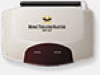
MRF-200 BASE STATION MRF-200 Details Red POWER LED lights when the MRF-200's power supply is plugged into an active AC outlet. Red STATUS LED lights when the MRF-200 receives an RF signal from the MX-800. The MRF-200's slots enable the Mounting Plate's matching guides to slide and "snap" into place for mounting on the wall. Front Blaster sends Infrared commands to all A/V components in the same cabinet space. The MRF-200 Mounting Plate Using the four enclosed screws, you can choose to fix the mounting plate to a wall or the back of your component cabinet. Page 3
-
 1
1 -
 2
2 -
 3
3 -
 4
4 -
 5
5 -
 6
6 -
 7
7 -
 8
8 -
 9
9 -
 10
10 -
 11
11 -
 12
12 -
13
-
14
-
15
-
16
 |
 |

Page 3
MRF-200 B
ASE
S
TATION
The MRF-200’s slots enable the
Mounting Plate’s matching guides
to slide and “snap” into place for
mounting on the wall.
Using the four enclosed
screws, you can choose to fix
the mounting plate to a wall or
the back of your component
cabinet.
Front Blaster sends Infrared com-
mands to all A/V components in
the same cabinet space.
The MRF-200 Mounting Plate
MRF-200 Details
Red P
OWER
LED lights when the
MRF-200’s power supply is plugged
into an active AC outlet.
Red S
TATUS
LED lights when the
MRF-200 receives an RF signal
from the MX-800.