URC MRF-200 Owners Manual - Page 8
A Standard MRF-200 System, Standard Installation - Step by Step
 |
View all URC MRF-200 manuals
Add to My Manuals
Save this manual to your list of manuals |
Page 8 highlights
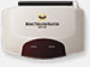
MRF-200 BASE STATION A Standard MRF-200 System A standard system utilizes no identical components and only one equipment location. However, you can add any number of MX-800 remote controls to your home! MX-800's are available as an accessory purchase without an MRF200 for standard system installations that already have an MRF-200. You can add any number of MRF-200 base stations in a standard system as well. If you need more than six flasher outputs you may add additional MRF200 receivers as needed by ordering an accessory MRF-200 base station. Do not change the factory default settings in RF Control section of MXEditor when you download to your MX-800's. You do not need to utilize MXEditor's Program Step 9 (RF Control), since the factory settings will work fine! Standard Installation - Step by Step Step 1 - Program and Download to the MX-800 Connect your MX-800 to your PC and program the IR commands and macros as you like. Since your MX-800 sends both IR and RF, you can test your programming as you go by pointing the MX-800 at the components and using MXEditor's TEST and Macro Play features if you place your laptop PC in the same room as the components (with the cabinet doors open and in line of sight). For a detailed explanation of how to program, use the downloadable Programming Manual or the animated Tutorial. Both are available as free downloads from the www.hometheatermaster.com website. Important Note: Do NOT power up the MRF-200 at this point. You need to test your IR commands and Macros line of sight via IR only at this point! Once you have completed and downloaded your programming to the MX-800 remote control, you are ready to test RF operation via the Front Blaster and (if necessary) the self-adhesive flashers that connect to the MRF-200's flasher line outputs. Step 2 - Place the MRF-200 The MRF-200 should be placed so that the Front Blaster will control as many of the system's A/V components as possible. If you are connecting the outboard flashers to the rear Flasher outputs only, the MRF-200 may be concealed and mounted to the rear wall or back of the system cabinet.The mounting plate slides apart from the receiver, screws to the wall or cabinet Page 5
-
 1
1 -
2
-
 3
3 -
 4
4 -
 5
5 -
 6
6 -
 7
7 -
 8
8 -
 9
9 -
 10
10 -
 11
11 -
 12
12 -
 13
13 -
14
-
15
-
16
 |
 |
