Uniden BC350C English Owners Manual - Page 13
Connecting the Antenna Plug, Mounting the Radio for Everyday Use, Connecting the Power Cord, - scanner antenna
 |
UPC - 064258650332
View all Uniden BC350C manuals
Add to My Manuals
Save this manual to your list of manuals |
Page 13 highlights
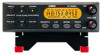
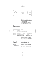
UB317Z (BC350C) 0916 9/16/03 12:42 PM Page 9 Connecting the Antenna Plug Connect the mobile antenna plug into the ANT connector on the rear panel. (For more information on antenna installation, please refer to the instruction guide that came with your antenna.) Mounting the Radio for Everyday Use The BC350C can be mounted using the mounting bracket (optional). This bracket is available from the Uniden parts department (see page 5) 1. Select an ideal location in your vehicle to mount the BC350C. Avoid a location that could interfere with your driving. In a passenger car, the ideal location is underneath the dashboard on the passenger side. 2. Use the mounting bracket (optional) as a template for marking the location of the mounting screws. Note: If there are screws already holding the dashboard, you can use the same screw holes to mount the bracket. 3. Drill the necessary holes and secure the mounting bracket in place using the screws provided. 4. Mount the radio to the bracket only after the wiring has been connected to the rear panel. Connecting the Power Cord Note: If you are not experienced in connecting accessories to the vehicle fuse box, please see your automotive dealer for advice on proper installation. Installation for Everyday Use: 1. Check the vehicle battery connections to determine which battery terminal (positive or negative) is grounded to the engine block or chassis. Most of today's vehicles use a negative ground. If your vehicle has a negative ground, follow Steps 2 and 3. Otherwise, skip to the note following Step 3. 2. Connect the RED wire of the DC power cord to the accessory contact in your vehicle's +13.8 VDC fuse box. 3. Connect the BLACK wire of the DC power cord to the negative side of the vehicle (usually the chassis). Note: In vehicles with a positive ground, the RED wire connects to the chassis and the BLACK wire connects to the accessory contact in the fuse box. 4. Insert the DC plug into the DC 13.8V jack on the back of the scanner. 9
-
 1
1 -
2
-
3
-
4
-
5
-
6
-
7
-
 8
8 -
 9
9 -
 10
10 -
 11
11 -
 12
12 -
 13
13 -
 14
14 -
 15
15 -
 16
16 -
 17
17 -
 18
18 -
19
-
20
-
21
-
22
-
23
-
24
-
25
-
26
-
27
-
28
-
29
-
30
-
31
-
32
-
33
-
34
-
35
-
36
-
37
-
38
-
39
-
40
 |
 |