Uniden MC535 English Owners Manual - Page 4
Indicators, Rear Panel Connectors - radio
 |
View all Uniden MC535 manuals
Add to My Manuals
Save this manual to your list of manuals |
Page 4 highlights
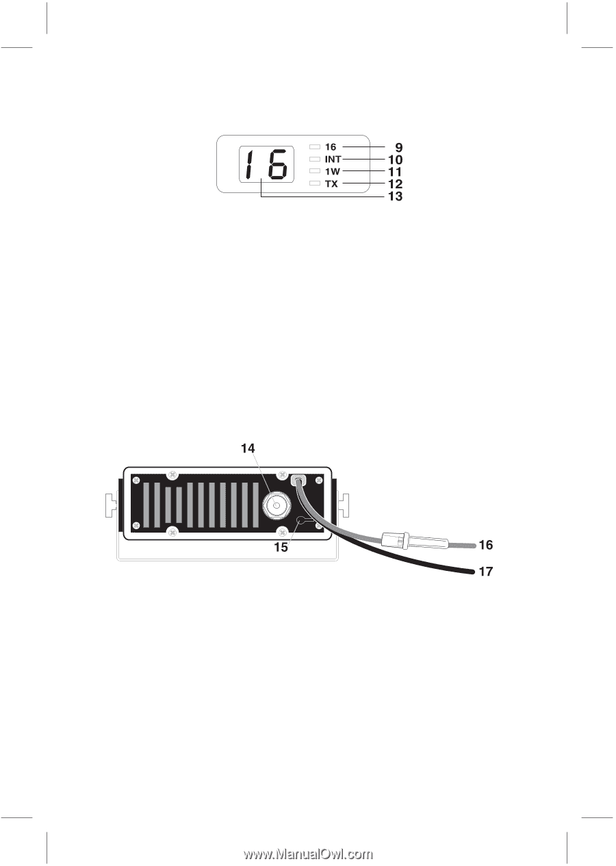
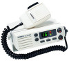
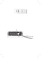
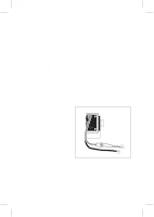
Color profile: Disabled Composite Default screen Indicators 9. 16 − Indicates that Channel 16 is selected. 10. INT − Indicates International Channel Mode. 11. 1W − Indicates transmitted output is 1 Watt. 12. TX (Transmit) − Indicates PTT switch is pressed and radio is transmitting. 13. LED Numerical Channel Display − Indicates Channel Number in use. Weather Channels are displayed as single digits (Example: 0, 1, 2, 3, etc.). Communication Channels are displayed as two digits (Example: 01, 02, 03, etc.). Rear Panel Connectors 14. Antenna Connector − Connect the antenna here using a PL259 type connector. 15. Remote Speaker Connector − An external 4 ohm, 4 watt speaker may be connected to this jack. The connecting wire must use the included 3.5mm miniature plug. 16. DC Power Cord with In-line Fuse Holder − Connect red power lead to positive power source. 17. DC Ground Cord − Connect black power lead to negative power source. C:\MANUALS7\mc535\Mc535.vp Tue Sep 08 10:53:55 1998
-
 1
1 -
 2
2 -
 3
3 -
 4
4 -
 5
5 -
 6
6 -
 7
7 -
 8
8 -
 9
9 -
 10
10 -
11
-
12
-
13
-
14
-
15
-
16
-
17
-
18
-
19
-
20
-
21
-
22
-
23
 |
 |