ViewSonic PJD5232 PJD5232, PJD5234, PJD7223 User Guide (English) - Page 13
Connection ports
 |
View all ViewSonic PJD5232 manuals
Add to My Manuals
Save this manual to your list of manuals |
Page 13 highlights
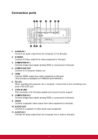
Connection ports 12 3 4 5 67 11 10 9 8 1. AUDIO IN 1 Connect an audio output from the Computer In1 to this jack. 2. S-VIDEO Connect S-Video output from video equipment to this jack. 3. COMPUTER IN 1 Connect image input signal (analog RGB or component) to this jack. 4. COMPUTER OUT Connect to a computer display, etc. 5. HDMI Connect HDMI output from video equipment to this jack. (This function is available for PJD5234 and PJD7223.) 6. RS-232 When operating the projector via a computer, connect this to the controlling computer's RS-232C port. 7. TYPE B USB This connector is for firmware update and mouse function support. 8. COMPUTER IN 2 Connect image input signal (analog RGB or component) to this jack. 9. VIDEO Connect composite video output from video equipment to this jack. 10. AUDIO OUT Connect to a speaker or other audio input equipment. 11. AUDIO IN 2 Connect an audio output from the Computer In2 or video to this jack. 6
-
 1
1 -
2
-
3
-
4
-
5
-
6
-
7
-
 8
8 -
 9
9 -
 10
10 -
 11
11 -
 12
12 -
 13
13 -
 14
14 -
 15
15 -
 16
16 -
 17
17 -
 18
18 -
19
-
20
-
21
-
22
-
23
-
24
-
25
-
26
-
27
-
28
-
29
-
30
-
31
-
32
-
33
-
34
-
35
-
36
-
37
-
38
-
39
-
40
-
41
-
42
-
43
-
44
-
45
-
46
-
47
-
48
-
49
-
50
-
51
-
52
-
53
-
54
-
55
-
56
-
57
-
58
 |
 |
