ViewSonic PJD6251 PJD6251 User Guide (English) - Page 13
Connection Ports - turning off
 |
UPC - 766907361117
View all ViewSonic PJD6251 manuals
Add to My Manuals
Save this manual to your list of manuals |
Page 13 highlights
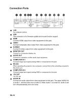
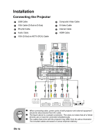
Connection Ports 1 2 3 45 6 7 8 9 10 11 12 1 LAN For network control. 2 USB This connector is for firmware update and mouse function support. 3 HDMI Connect HDMI output from video equipment to this jack. 4 VIDEO Connect composite video output from video equipment to this jack. 5 S-VIDEO Connect S-Video output from video equipment to this jack. 6 MONITOR OUT Connect to a computer display, etc. 7 AUDIO OUT Connect to a speaker or other audio input equipment. 8 COMPUTER IN 1 Connect image input signal (analog RGB or component) to this jack. 9 RS-232 When operating the projector via a computer, connect this to the controlling computer's RS-232C port. 10 COMPUTER IN 2 Connect image input signal (analog RGB or component) to this jack 11 12V OUT 12V DC out 12 AUDIO IN Connect an audio output from video equipment to this jack. The upper AUDIO IN is Audio 1, and the lower one is Audio 2. When Audio 1 is turned on, Audio 2 will turn off automatically and vice versa. EN-10
-
 1
1 -
2
-
3
-
4
-
5
-
6
-
7
-
 8
8 -
 9
9 -
 10
10 -
 11
11 -
 12
12 -
 13
13 -
 14
14 -
 15
15 -
 16
16 -
 17
17 -
 18
18 -
19
-
20
-
21
-
22
-
23
-
24
-
25
-
26
-
27
-
28
-
29
-
30
-
31
-
32
-
33
-
34
-
35
-
36
-
37
-
38
-
39
-
40
-
41
-
42
-
43
-
44
-
45
-
46
-
47
-
48
-
49
-
50
-
51
-
52
-
53
-
54
-
55
-
56
-
57
-
58
-
59
 |
 |
