ViewSonic VOT120 User Guide - Page 8
s, Tables
 |
UPC - 766907397413
View all ViewSonic VOT120 manuals
Add to My Manuals
Save this manual to your list of manuals |
Page 8 highlights
Figures Figure 1 Front Panel 3 Figure 2 Rear Panel 5 Figure 3 Connecting the DVI cable 7 Figure 4 Connecting USB mouse & keyboard 8 Figure 5 Network cable with RJ45 connector 8 Figure 6 Turning on the system 9 Figure 7 Using a Kensington lock 9 Figure 8 Computer Stand 10 Figure 9 VESA mounting (1 10 Figure 10 VESA mounting (2 11 Tables Table 1 VOT120 product specifications 2 Table 2 BIOS Main Menu 13 Table 3 IDE Device Setting Menu 13 Table 4 System Information 14 Table 5 Advanced Menu 15 Table 6 OnBoard Peripherals Configuration Settings 15 Table 7 Hardware Health Configuration 16 Table 8 Boot Menu 17 Table 9 Chipset Menu 18 Table 10 Power Menu 19 Table 11 Security Menu 20 Table 12 Exit Menu 21 ViewSonic VOT120
-
 1
1 -
2
-
 3
3 -
 4
4 -
 5
5 -
 6
6 -
 7
7 -
 8
8 -
 9
9 -
 10
10 -
 11
11 -
 12
12 -
 13
13 -
14
-
15
-
16
-
17
-
18
-
19
-
20
-
21
-
22
-
23
-
24
-
25
-
26
-
27
-
28
-
29
-
30
-
31
-
32
-
33
-
34
-
35
-
36
-
37
-
38
 |
 |

ViewSonic
VOT120
Figures
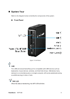
Figure 1 Front Panel
...................................................................................................
3
Figure 2 Rear Panel
...................................................................................................
5
Figure 3 Connecting the DVI cable
............................................................................
7
Figure 4 Connecting USB mouse & keyboard
............................................................
8
Figure 5 Network cable with RJ45 connector
.............................................................
8
Figure 6 Turning on the system
..................................................................................
9
Figure 7 Using a Kensington lock
...............................................................................
9
Figure 8 Computer Stand
.........................................................................................
10
Figure 9 VESA mounting (1)
.....................................................................................
10
Figure 10 VESA mounting (2)
...................................................................................
11
Tables
Table 1 VOT120 product specifications
......................................................................
2
Table 2 BIOS Main Menu
.........................................................................................
13
Table 3 IDE Device Setting Menu
.............................................................................
13
Table 4 System Information
......................................................................................
14
Table 5 Advanced Menu
...........................................................................................
15
Table 6 OnBoard Peripherals Configuration Settings
...............................................
15
Table 7 Hardware Health Configuration
....................................................................
16
Table 8 Boot Menu
...................................................................................................
17
Table 9 Chipset Menu
...............................................................................................
18
Table 10 Power Menu
...............................................................................................
19
Table 11 Security Menu
............................................................................................
20
Table 12 Exit Menu
...................................................................................................
21