ViewSonic
VOT125
Figures & Tables
Figure 1 Front Panel
....................................................................................
3
Figure 2 Rear Panel
.....................................................................................
5
Figure 3 Connect the HDMI cable
................................................................
7
Figure 4 Connect the DVI cable
...................................................................
8
Figure 5 Connecting USB mouse & keyboard
..............................................
8
Figure 6 Network cable with RJ45 connector
...............................................
9
Figure 7 Turing on the system
.....................................................................
9
Figure 8 VESA mounting (1)
......................................................................
10
Figure 9 VESA mounting (2)
......................................................................
10
Figure 10 Use a Kensington lock
...............................................................
11
Figure 11 Computer Stand
.........................................................................
12
Figure 12 Stand Dimension
........................................................................
12
Table 1 VOT125 product specifications
........................................................
2
Table 2 BIOS Main Menu
...........................................................................
14
Table 3 IDE Device Setting Menu
..............................................................
14
Table 4 System Information
........................................................................
15
Table 5 Advanced Menu
.............................................................................
15
Table 6 CPU Configuration
........................................................................
16
Table 7 OnBoard Peripherals Configuration Settings
................................
16
Table 8 Hardware Health Configuration
.....................................................
17
Table 9 Boot Menu
.....................................................................................
18
Table 10 Chipset Menu
..............................................................................
19
Table 11 Power Menu
.................................................................................
20
Table 12 Security Menu
.............................................................................
21
Table 13 Exit Menu
....................................................................................
21
 1
1 3
3 4
4 5
5 6
6 7
7 8
8 9
9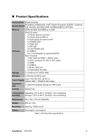 10
10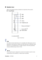 11
11 12
12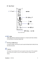 13
13