ViewSonic VP2330WB Service Manual - Page 16
Red Video for DVI-A only
 |
UPC - 766907150919
View all ViewSonic VP2330WB manuals
Add to My Manuals
Save this manual to your list of manuals |
Page 16 highlights
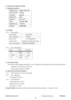
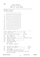
2.3 Video signal connector for digital input: 29pin DVI-D,DVI-A connector CN2 25 1 RX2RX2+ GND 2 3 4 RX4RX4+ SCL SDA VS 5 6 7 8 RX1RX1+ GND RX3- 9 10 11 12 13 RX3+ 5V GND HP 14 15 16 17 RX0RX0+ GND 18 19 20 RX5RX5+ GND RXC+ RXC- 21 22 23 24 RED GRN BLU HS C1 C2 C3 C4 C5 GND 26 DVI-I Pin No. Signal Name Description 1 RX2- TMDS negative differential input, channel 2 2 RX2+ TMDS positive differential input, channel 2 3 GND Logic Ground 4 RX4- Reserved. No connection 5 RX4+ Reserved. No connection 6 SCL DDC2B Clock 7 SDA DDC2B Data 8 VS Reserved. No connection 9 RX1- TMDS negative differential input, channel 1 10 RX1+ TMDS positive differential input, channel 1 11 GND Logic Ground 12 RX3- Reserved. No connection 13 RX3+ Reserved. No connection 14 +5V Power 15 GND Logic Ground 16 HP SENSE Pin, Pull High 17 RX0- TMDS negative differential input, channel 0 18 RX0+ TMDS positive differential input, channel 0 19 GND Logic Ground 20 RX5- Reserved. No connection 21 RX5+ Reserved. No connection 22 GND Logic Ground 23 RXC+ TMDS positive differential input, reference clock 24 RXC- TMDS negative differential input, reference clock C1 RED Red Video for DVI-A only C2 GRN Green Video for DVI-A only C3 BLU BlueVideo for DVI-A only C4 HS Horizontal Sync C5 GND GND ViewSonic Corporation Confidential - Do Not Copy 13 VP2330wb
-
 1
1 -
2
-
3
-
4
-
5
-
6
-
7
-
8
-
9
-
10
-
 11
11 -
 12
12 -
 13
13 -
 14
14 -
 15
15 -
 16
16 -
 17
17 -
 18
18 -
 19
19 -
 20
20 -
 21
21 -
22
-
23
-
24
-
25
-
26
-
27
-
28
-
29
-
30
-
31
-
32
-
33
-
34
-
35
-
36
-
37
-
38
-
39
-
40
-
41
-
42
-
43
-
44
-
45
-
46
-
47
-
48
-
49
-
50
-
51
-
52
-
53
-
54
-
55
-
56
-
57
-
58
-
59
-
60
-
61
-
62
-
63
-
64
-
65
-
66
-
67
-
68
-
69
-
70
-
71
 |
 |
