Viking DFWB300R Installation Instructions - Page 12
Home Security System Connection, Wine Cellar Installation
 |
View all Viking DFWB300R manuals
Add to My Manuals
Save this manual to your list of manuals |
Page 12 highlights
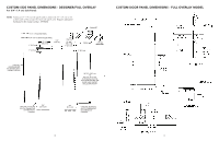
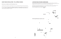
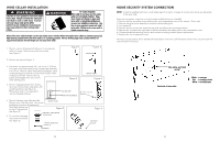
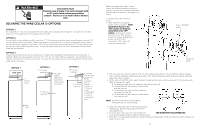
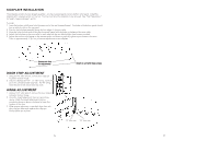
WINE CELLAR INSTALLATION WARNING Use two or more people to move and install wine cellar. Failure to follow this instruction can result in back or other injury. To avoid personal injury, wear gloves when performing any installation procedure and wear eye protection when cutting metal straps. WARNING TIP OVER HAZARD Wine cellar is top heavy and tips easily when not completely installed. Keep door closed and shelves in place until wine cellar is completely installed and secured per installation instructions. Use two or more people to move and install wine cellar. Failure to do so can result in death or serious injury. Most of the wine cellar's weight is at the top. Extra care is needed when moving the wine cellar to prevent tipping. Do Not remove protective film until wine cellar is in operating position. All four leveling legs must contact the floor to support and stabilize the full weight. Do not drop wine cellar. 1. Remove exterior shipping materials prior to moving wine cellar into home. Remove top and bottom strap (see Figure 1). Figure 1 Figure 2 2. Remove top cap (see Figure 1). 3. Cut carton rear approximately 1/4" (.64 cm) to 1" (2.5 cm) from right corner (see figure 2) with a utility knife extended 1/4" (.6 cm). Remove carton and exterior packaging. Save cardboard shipping material to protect floor surface when installing wine cellar. Remove anti-tip boards and kickplate from rear of wine cellar (see Figure 3). 4. Remove shipping brackets from skid by removing 4 bolts (2 each side) with a 1/2" socket head driver (see Figure 4) •Tilting wine cellar is not required to remove shipping brackets. Figure 3 BACK VIEW Figure 4 KICKPLATE ANTI-TIP BOARDS (4) 1/2" (1.3 cm) BOLTS 5. Slip cart between wine cellar and skid. Remove wine cellar from skid. Use excess BACK VIEW packaging to protect decorative trim. Verify that leveling legs are up (0" adjustment) Figure 5 (see Figure 5). PROTECT TRIM FROM 6. To avoid floor damage, STRAPPING use protective material. (see Figure 6). FRONT LEVELING LEGS (2) SKID Figure 6 PROTECT FLOOR 22 HOME SECURITY SYSTEM CONNECTION NOTE: Contact a qualified electrician or authorized agent from alarm company to connect your home security system to the wine cellar. Home security system connection must be hooked up before the unit is installed. 1) Remove the four mounting screws attaching the unit compartment cover to the cabinet. (2 per side) 2) Remove the grille louver assembly to access the black safety grille. 3) Turn power off. 4) Remove the four screws that attach the top grille assembly to the mounting brackets. 5) Remove the 3 screws at the right side of the unit that attach the safety grille to the compartment cover. 6) Choose the desired switching position and connect according to alarm system requirements. 7) Replace the unit compartment cover. The home security system will be activated if temperatures in the wine cellar fluctuate outside of the set point by 5° for and extended time period. Red, white, and black wiring* Back side of wine cellar *Black = common Red = normally closed White = normally open 23
-
 1
1 -
2
-
3
-
4
-
5
-
6
-
 7
7 -
 8
8 -
 9
9 -
 10
10 -
 11
11 -
 12
12 -
 13
13 -
 14
14
 |
 |
