Viking QSC200SS Installation Instructions - Page 2
Important: Please Read And Follow - direct
 |
View all Viking QSC200SS manuals
Add to My Manuals
Save this manual to your list of manuals |
Page 2 highlights
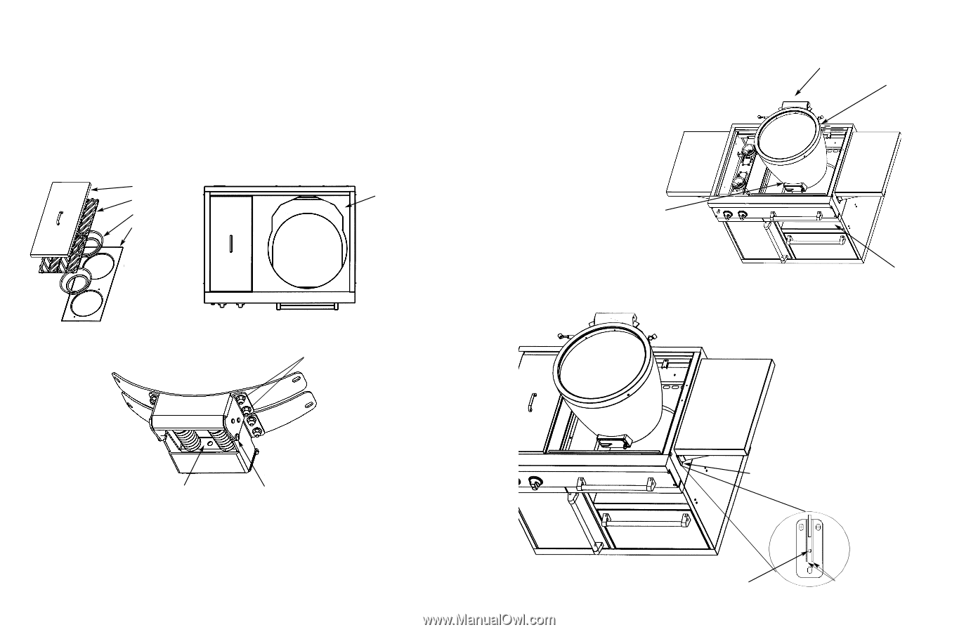
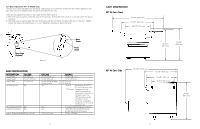
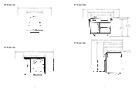
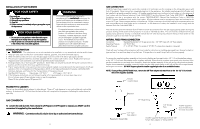
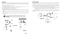
IMPORTANT: PLEASE READ AND FOLLOW 1. Before beginning, please read these instructions completely and carefully. 2. Do not remove permanently affixed labels, warnings, or plates from product. To mount the cooker to the cart: Always wear gloves when installing the cooker. Although the cooker and cart is deburred prior to shipment, some edges may still be sharp enough to cause injury during handling. 1. Remove the stainless steel side burner cover, side burner grates, burner bowls and grate support. (41" W. models only) 2. Remove the top from the cart. (See Figure 1) CAUTION: Keep hands and fingers away fro spring area. 3. Install two (2) shipping screws, (one set on each side). (See Figure 2) Remove the two (2) top nuts and washers on each side of the hinge mount. 4. Remove all inside parts. Stainless cover Grates Burner bowls Grate support Cart top Figure 1 Remove the (2) top nuts and washers on each side of hinge Figure 2 CAUTION Keep hands and fingers out of spring area. Lift from bottom or inside front of hinge. Install (2) shipping screws (one on each side) 2 5. With a minimum of two people, place the cooker on the cooker shelf located in the cart. Also, make sure the cooker is placed on the mounting bracket located on the cart directly under the hinge. The hinge and the inside damper vent should be used for hand holds. (See Figure 3). 6. Re-install dome, hinge nuts and washers. Remove shipping screws from each side of hinge. Replace inside parts Hinge Mounting Bracket (located behind cooker on cart directly under hinge) Damper vent Figure 3 Cooker shelf Leveling the Side Shelves To level the side shelves, lift the shelf so that the shelf adjustment screw is visible between the two supports on the shelf brackets. Turn the screw with the included 3/32" (.2 cm) allen wrench counter clockwise to raise the shelf and clockwise to lower the shelf. (See Figure 4) support bracket screws Figure 4 Shelf adjustment screw 3 Supports Front View
-
 1
1 -
 2
2 -
 3
3 -
 4
4 -
 5
5 -
 6
6 -
 7
7 -
 8
8
 |
 |