Viking QSC200SS Installation Instructions - Page 5
For Your Safety, Warning - appliances
 |
View all Viking QSC200SS manuals
Add to My Manuals
Save this manual to your list of manuals |
Page 5 highlights
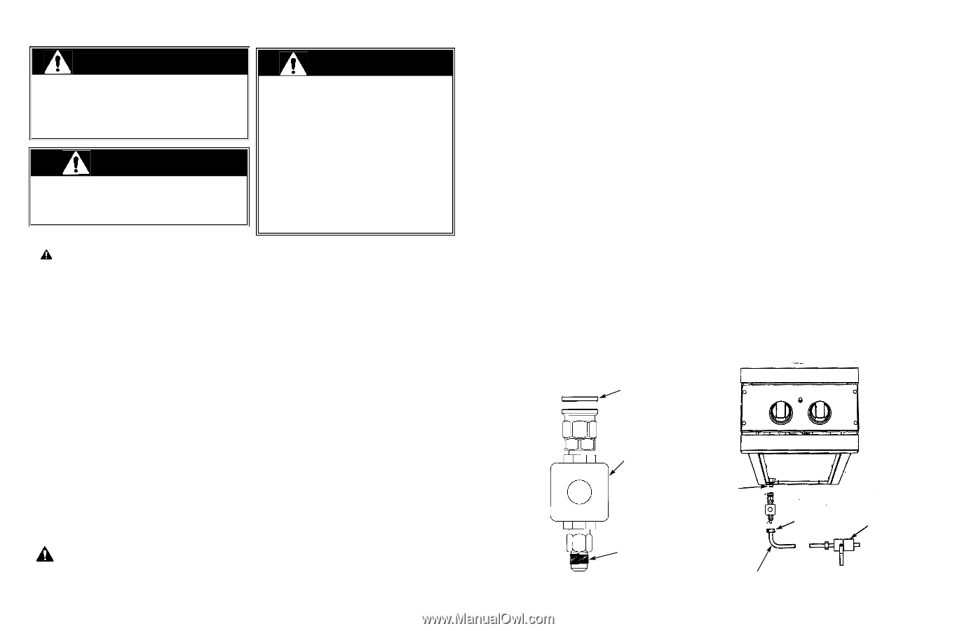
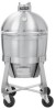
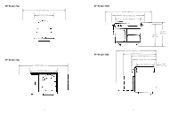
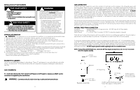
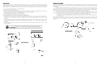
INSTALLATION OF SIDE BURNERS FOR YOUR SAFETY WARNING If you smell gas: 1. Shut off gas to the appliance. 2. Extinguish any open flame. 3. Open lid. 4. If odor continues, immediately call your gas supplier or your fire department. FOR YOUR SAFETY 1. Do not store or use gasoline or other flammable vapors and liquids in the vicinity of this or any other appliance. 2. Any LP cylinder not connected for use shall not be stored in the vicinity of this or any other appliance. If not installed, operated and maintained in accordance with the manufacturer's instructions, this product could expose you to substances in fuel or fuel combustion which can cause death or serious illness and which are known to cause cancer, birth defects or other reproductive harm. For example, benzene is a chemical which is part of the gas supplied to the cooking product. It is consumed in the flame during combustion. However, exposure to a small amount of benzene is possible if a gas leak occurs. Formaldehyde and soot are byproducts of incomplete combustion. Properly adjusted burners with a bluish rather than yellow flame minimize incomplete combustion. GENERAL INFORMATION 1. WARNING: This side burner cart is not intended to be installed in or on recreational vehicles and/or boats. 2. Keep grill area clear and free from combustible materials, gasoline, and other flammable vapors. 3. When the side burners are not in use, the gas supply must be turned off at the LP gas supply cylinder. 4. The pressure regulator and hose assembly supplied with the outdoor grill must be used. Replacement pressure regulators and hose assemblies must be those specified by the manufacturer. 5. Finding a leak is not a "do-it-yourself" procedure. Some leaks can only be found with the burner control in the on position and this must be done by a qualified technician. 6. The LP supply cylinder to be used must be constructed and marked in accordance with the specifications for LP-gas cylinders of the U.S. Department of Transportation (DOT) or the National Standard of Canada, CAN/CSA-B339, Cylinders, Spheres, and Tubes for the Transportation of Dangerous Goods. 7. Gas Manifold Pressure - Natural gas - 4.0" W.C.P. LP/Propane - 10.0" W.C.P. 8. If the following instructions are not followed exactly, a fire causing death or serious injury may occur: -Do not store a spare LP gas cylinder under or near this appliance. -Never fill the cylinder beyond 80 percent full. PROXIMITY TO CABINETS The cart can be installed directly adjacent to side cabinets. There is 0" side clearance to non-combustible and combustible surfaces. A minimum of 6" (15.2 cm) from the back of the unit is required for the purpose of allowing the cooker dome to open fully. GAS CONVERSION To convert the side burners from natural to LP/Propane or LP/Propane to natural, you MUST use the conversion kit supplied by the manufacturer. WARNING: Conversions should only be done by an authorized service technician. 8 GAS CONNECTION Verify the type of gas supply to be used, either natural or LP, and make sure the marking on the rating plate agrees with that of the supply. Never connect an unregulated gas line to the appliance. An installer supplied gas shut-off valve must be installed in an easily accessible location. All installer supplied parts must conform to local codes, or in the absence of local codes, with the National electrical Code, ANSI/NFPA 70 and the National Fuel Code, ANSI Z223.1. In Canada: Installation must be in accordance with the current CAN/CGA-B149.1, Natural Gas Installation Code or CAN/CGAB149.2, Propane Installation Code and/or local codes. All pipe sealants must be an approved type and resistant to the actions of LP gas. Never use pipe sealant on flare fittings. All gas connections should be made by a competent technician and in accordance with local codes and or ordinances. In the absence of codes, the installation must comply with the National Fuel Gas Code ANSI Z223.1. The side burners and the individual shut-off valve must be disconnected from the gas supply piping system during any pressure testing of that system at test pressures in excess of 1/2 PSIG (3.5 kPa). The unit must be isolated from the gas supply piping system by closing its individual manual shut-off valve during any pressure testing of that system at test pressures equal to or less than 1/2 psi (3.5 kPa). NATURAL FIXED PIPING CONNECTION Connection: Standard Residential 1/2" ID gas service line - 1/2" NPT male with 1/2" flare adapter. Operating Pressure: 4.0" W.C.P. Nat. Supply Pressure: 6" to 14" W.C.P. Nat. If in excess of 14" W.C.P., a step-down regulator is required. Check with your local gas utility company or with local codes for instructions on installing gas supply lines. Be sure to check on type and size of run and how deep to bury the lines. If the gas line is too small, the grill will not function properly. To connect the supplied regulator assembly to the incoming flexible gas line, attach with a 1/2" (1.3 cm) female flare adaptor to the 1/2" (1.3 cm) male flare adaptor on the regulator assembly. Ensure that the regulator arrow points in the direction of the gas flow towards the unit and away from the supply. Attach the regulator assembly to the grill unit by pulling back the female coupler sleeve towards the regulator. Insert the coupler into the male coupler fitting on the grill until the sleeve snaps forward securing the connection. DO NOT forget to place the installer supplied gas valve in an accessible location. NOTE: If using a Viking GSH12 flexible hose, remove the 3/8" flare adapter and attach hose to the the 1/2" (1.3 cm) male flare on the regulator assembly. Female coupler sleeve Regulator 1/2" Male fitting 1/2" male flare adaptor Regulator Assembly 1/2" female flare Installer supplied shut-off valve must be easily accessible Installer supplied flexible gas line with 1/2" female flare adaptor or Viking GSH12 9
-
 1
1 -
 2
2 -
 3
3 -
 4
4 -
 5
5 -
 6
6 -
 7
7 -
 8
8
 |
 |