Viking RDMOR200SS Installation Instructions - Page 6
Viking RDMOR200SS Manual
 |
View all Viking RDMOR200SS manuals
Add to My Manuals
Save this manual to your list of manuals |
Page 6 highlights
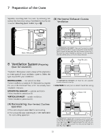
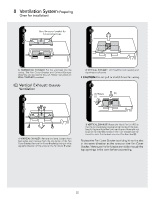
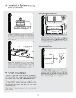
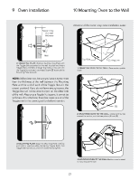
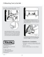
8 Ventilation System (Preparing Oven for Installation) # figure Mounting Scale Plate % figur e figure 8 Scale Plates Mounting Plate 4) VERTICAL EXHAUST: Attach the Fan Cover Bracket to unit with the 2 screws from back edge and 3 screws from the top center of the Fan Cover Bracket, which were removed in Step 1. The Hood Fan Unit is now rotated for vertical exhaust operation. $ figure 7 Exhaust Damper Assembly OVEN INSTALLATION: The Scale Plates are used to help locate the mounting plate. Attach 2 Scale Plates 8 with tape (not included). See Figure % and WALL TEMPLATE for locations. After securing the mounting plate, remove and discard the Scale Plates. Mounting Plate & figure Toggle Bolt 5) VERTICAL EXHAUST: Attach the Exhaust Damper Assembly to the fan cover on the top of the outercase cabinet by sliding it into the slits in the same direction as the arrow. Use 1 Tapping Screw 4 x 12 mm 4 from the INSTALLATION HARDWARE and tighten into place. Mounting Plate 9 Oven Installation This oven cannot be properly installed without referring to the mounting instructions found on wall and top cabinet templates. The next step is to read and follow mounting information on wall and top cabinet templates. This oven must be attached to at least one wall stud. See WALL CONSTRUCTION. When done with templates, proceed to mounting scale plate section. 1) MOUNTING PLATE: Separate 4 Toggle Bolts 2, packed in the INSTALLATION HARDWARE, from the Toggle Nuts. Match 5/8" holes (not in studs), drilled through WALL TEMPLATE into wall to corresponding holes on Mounting Plate. Insert Toggle Bolts into matched openings on Mounting Plate. Put Toggle Nuts on Toggle Bolts. E6
-
 1
1 -
 2
2 -
 3
3 -
 4
4 -
 5
5 -
 6
6 -
 7
7 -
 8
8 -
 9
9 -
 10
10 -
 11
11 -
 12
12 -
13
-
14
-
15
-
16
-
17
-
18
-
19
-
20
-
21
-
22
-
23
-
24
 |
 |
