Viking TVDR361 Installation Instructions
Viking TVDR361 Manual
 |
View all Viking TVDR361 manuals
Add to My Manuals
Save this manual to your list of manuals |
Viking TVDR361 manual content summary:
- Viking TVDR361 | Installation Instructions - Page 1
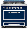
Installation GUIDE Tuscany Freestanding Dual Fuel Ranges TVDR3604B, TVDR3602G, CTVDR3604B, CTVDR3602G TVDR4806B, TVDR4804G, TVDR4804I, TVDR4802GI, TVDR4804F CTVDR4806B, CTVDR4804G, CTVDR4804I, CTVDR4802GI, CTVDR4804F TVDR6608B, TVDR6606G, TVDR6606I, TVDR6606F CTVDR6608B, CTVDR6606G, - Viking TVDR361 | Installation Instructions - Page 2
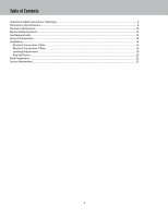
Table of Contents Important Safety Instructions / Warnings ...3 Dimensions /Specifications ...6 Clearance Dimensions...10 Electrical Requirements ...12 Gas Requirements...13 Connection 4-Wire...16 Leveling/Adjustments ...18 Anti-Tip Device...20 Final Preparation...22 Service Information ...23 2 - Viking TVDR361 | Installation Instructions - Page 3
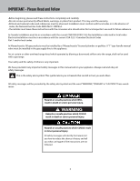
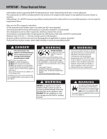
Gas Code ANSI Z223.1 INFPA54. •The installer must leave these instructions with the consumer who should retain for local inspector's use and others is very important. We have provided many important safety messages in this manual and on your appliance. Always read and obey all safety messages. This - Viking TVDR361 | Installation Instructions - Page 4
Range, LLC will NOT warranty any problems resulting from GFI outlets which are instructions. • If you cannot reach your gas supplier, call the fire department. Installation and service must be performed by a qualified installer, service death; follow information in this manual exactly to prevent a fire - Viking TVDR361 | Installation Instructions - Page 5
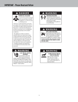
. WARNING GAS LEAK HAZARD To avoid risk of personal injury or death; leak testing of the appliance must be conducted according to the manufacturer's instructions. Before placing appliance in operation, always check for gas leaks with soapy water solution. • DO NOT USE AN OPEN FLAME TO CHECK FOR GAS - Viking TVDR361 | Installation Instructions - Page 6
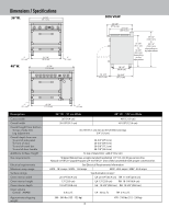
(35.2 cm) To top of island trim: add 4" (10.2 cm) Shipped Natural Gas, accepts standard residential 1/2" (1.3 cm) ID gas service line. Natural 5.0"W.C.P./ Liquid Propane L/P 10.0"W.C.P. Unit is field convertible with proper conversion kit. See Electrical Requirements Information 240V - 18.5 amps - Viking TVDR361 | Installation Instructions - Page 7
Dimensions / Specifications Surface BTU Rates 36" W /4 Surface Burners 36" W /2 Surface Burners/Griddle 8,500 Nat/ 7,700 LP 20,500 Nat/ 18,500 LP 13,500 Nat/ 12,500 LP 20,500 Nat/ 18,500 LP 13,500 Nat/ 12,500 LP 20,500 Nat/ 18,500 LP 2 kW 48" W /6 Surface Burners 8,500 Nat/ 7,700 LP 20,500 Nat - Viking TVDR361 | Installation Instructions - Page 8
(35.2 cm) To top of island trim: add 4" (10.2 cm) Shipped Natural Gas, accepts standard residential 1/2" (1.3 cm) ID gas service line. Natural 5.0"W.C.P./ Liquid Propane L/P 10.0"W.C.P. Unit is field convertible with proper conversion kit. See Electrical Requirements Information 240V - 31.1 amps - Viking TVDR361 | Installation Instructions - Page 9
Dimensions / Specifications Surface BTU Rates 66" W /8 Surface Burners 8,500 Nat/ 7,700 LP 20,500 Nat/ 18,500 LP 13,500 Nat/ 12,500 LP 20,500 Nat/ 18,500 LP 13,500 Nat/ 12,500 LP 20,500 Nat/ 18,500 LP 13,500 Nat/ 12,500 LP 20,500 Nat/ 18,500 LP 66" W /6 Surface Burners/Griddle 8,500 Nat/ 7,700 - Viking TVDR361 | Installation Instructions - Page 10
Clearance Dimensions •This range may be installed directly adjacent to existing 36" (91.4 cm) high base cabinets. IMPORTANT: The side panel MUST be 3/8" (.95 cm) above the adjacent base cabinet countertop. This can be accomplished by raising the unit using the adjustment spindles on the legs. •The - Viking TVDR361 | Installation Instructions - Page 11
result in the bottom of the hood being 66" (167.6 cm) to 72" (182.9 cm) above the floor. Refer to the range hood installation instructions for additional information. These dimensions provide for safe and efficient operation of the hood. 66" min (167.6 cm) to Wall Installation 72" max (182.9 cm - Viking TVDR361 | Installation Instructions - Page 12
is normally related to the location of a receptacle with respect to any significant sources of water or moisture. •Manufacturer will NOT warranty any problems resulting from GFI outlets which are not installed properly or do not meet the requirements below. If the use of a GFI is required, it should - Viking TVDR361 | Installation Instructions - Page 13
propane (LP) gas. Before beginning installation verify that the model is compatible with the intended gas supply. Manual shut-off valve: This installer-supplied valve must be installed in the gas service line before the appliance in the gas stream and in a location where it can be reached quickly in - Viking TVDR361 | Installation Instructions - Page 14
General Information READ AND FOLLOW ALL WARNING AND CAUTION INFORMATION WHEN INSTALLING THIS APPLIANCE. • All openings in the wall behind the appliance and in the floor under the appliance must be sealed. • Do not obstruct the flow of combustion and ventilation air. CAUTION Avoid any damage to oven - Viking TVDR361 | Installation Instructions - Page 15
Installation Electrical Connection 3-Wire WARNING ELECTRICAL SHOCK HAZARD To avoid risk of electrical shock, personal injury or death; verify your appliance has been properly grounded in accordance with local codes or in absence of codes, with the National Electrical Code (NEC) ANSI/ NFPA-70 - - Viking TVDR361 | Installation Instructions - Page 16
Electrical Connection 3-Wire (con't) 5 1 6 Push supply cord toward terminal block to relieve strain, reattach supply cord strain relief bracket over supply cord. Electrical Connection 4-Wire WARNING ELECTRICAL SHOCK HAZARD To avoid risk of electrical shock, personal injury or death; verify your - Viking TVDR361 | Installation Instructions - Page 17
Electrical Connection 4-Wire (con't) 3 4 Remove grounding screw. Cut-off and discard ground strap. 5 Feed supply cord up through hole in bottom of range back. 6 Attach ground lead (green) with ground screw that was removed. 7 1 Attach line #1 (red) and line #2 (black) leads to outside - Viking TVDR361 | Installation Instructions - Page 18
Installation Leveling/Adjustments 1 2 Measure the four corners in cutout area to verify if flooring is level. 3 For uneven or sloped floors, level unit with metal shims only, as the adjustment required may exceed the thread available in the legs. 4 Move unit into opening. 5 (03.9/58"cm) Check - Viking TVDR361 | Installation Instructions - Page 19
Installation Leveling/Adjustments (con't) 7 Set the high corner of range so that the top of side trim is 3/8" (0.95 cm) above countertop. Level range to high corner. 19 - Viking TVDR361 | Installation Instructions - Page 20
Installation Anti-tip Device Installation Your range is shipped standard with two types of anti-tip devices. Type 1 is a wall mount device which can be used for all installation applications. Type 2 is a floor mount device which can be used for all applications other than when the range is installed - Viking TVDR361 | Installation Instructions - Page 21
Installation Floor Mount Installation 1 (3.81-c1m/)2" (281-1.6/2cm" ) Ø(.321/c8m") Locate anti-tip bracket hook on the floor 8-1/2" (21.6 cm) from side cabinet and 1-1/2" (3.8 cm) from rear wall. Mark and drill 1/8" (.32 cm) holes where bracket will be located. 3 1 1 2 Attach bracket to back of - Viking TVDR361 | Installation Instructions - Page 22
1 WARNING GAS LEAK HAZARD To avoid risk of personal injury or death; leak testing of the appliance must be conducted according to the manufacturer's instructions. Before placing appliance in operation, always check for gas leaks with soapy water solution. • DO NOT USE AN OPEN FLAME TO CHECK FOR GAS - Viking TVDR361 | Installation Instructions - Page 23
authorized service agency, or if you continue to have service problems, contact 1-888-845-4641, or write to: VIKING RANGE, LLC PREFERRED SERVICE 111 Front service is ever required. Model number Serial number Date of purchase Date installed Dealer's name Address These installation instructions - Viking TVDR361 | Installation Instructions - Page 24
F21410B EN Viking Range, LLC 111 Front Street Greenwood, Mississippi 38930 USA (662) 455-1200 For product information, call 1-888-(845-4641) or visit vikingrange.com in the US or brigade.ca in Canada (080116)
-
 1
1 -
 2
2 -
 3
3 -
 4
4 -
 5
5 -
 6
6 -
 7
7 -
8
-
9
-
10
-
11
-
12
-
13
-
14
-
15
-
16
-
17
-
18
-
19
-
20
-
21
-
22
-
23
-
24
 |
 |

Installation
GUIDE
Tuscany Freestanding Dual Fuel Ranges
TVDR3604B, TVDR3602G, CTVDR3604B, CTVDR3602G
TVDR4806B, TVDR4804G, TVDR4804I, TVDR4802GI, TVDR4804F
CTVDR4806B, CTVDR4804G, CTVDR4804I, CTVDR4802GI, CTVDR4804F
TVDR6608B, TVDR6606G, TVDR6606I, TVDR6606F
CTVDR6608B, CTVDR6606G, CTVDR6606I, CTVDR6606F