Viking VCSO210SS Installation Instructions
Viking VCSO210SS Manual
 |
View all Viking VCSO210SS manuals
Add to My Manuals
Save this manual to your list of manuals |
Viking VCSO210SS manual content summary:
- Viking VCSO210SS | Installation Instructions - Page 1
national codes and ordinances. • The installer should leave these instructions with the consumer who should retain for local inspector's use and for future reference. • This built-in trim kit is designed for use only with Viking COMBI STEAM/CONVECT™ OVEN. • Your oven can be built into a cabinet or - Viking VCSO210SS | Installation Instructions - Page 2
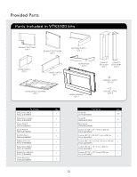
Provided Parts Parts Included in VTKS300 kits Exhaust Duct Back QTY 1 Exhaust Duct Upper QTY 1 Divide Plate L QTY 1 Divide Plate R QTY 1 Rectifier Plate L QTY 1 Rear Spacer QTY 1 Exhaust Duct Bottom QTY 1 Frame - Viking VCSO210SS | Installation Instructions - Page 3
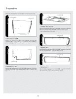
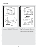
Preparation Follow the directions from 1 to 5 to attach cushions to some parts. 1 CUSHIONS 1 CUSHIONS 1 3 A CUSHIONS 3 1. EXHAUST DUCT UPPER Remove the backing paper from each CUSHION 1. Attach the CUSHIONS 1 to each side flange of the Exhaust Duct Upper - Viking VCSO210SS | Installation Instructions - Page 4
support the weight of the oven (about 51 lbs.,23 kg) and should be level for proper operation of the oven. NOTE: While the proper functioning of the oven oven performance. 2 DIVIDE PLATE L DIVIDE PLATE R SCREW (A) EXHAUST DUCT BOTTOM SCREW (A) FIGURE 2-A CATCHES SCREW (A) STEP 2: INSTALLATION - Viking VCSO210SS | Installation Instructions - Page 5
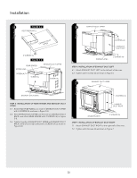
projections at the 4 corners of EXHAUST DUCT BOTTOM as shown in Figure 3-A. STEP 4: EXHAUST DUCT BACK INSTALLATION 4.1 Remove 2 screws (#1) from upper both sides of the oven as shown in Figure 4-A to install the EXHAUST DUCT BACK. (Save 2 screws to be used at step 4.2.) 4.2 Secure EXHAUST DUCT BACK - Viking VCSO210SS | Installation Instructions - Page 6
OF EXHAUST DUCT LEFT 6.1 Attach EXHAUST DUCT LEFT to the left wall of the oven. 6.2 Tighten with 6 screws (A) as shown in Figure 6. 7 EXHAUST DUCT UPPER EXHAUST DUCT BACK 2 SCREWS (A) STEP 5: INSTALLATION OF REAR SPACER and EXHAUST DUCT UPPER 5.1 Attach RECTIFIER PLATE L to inside of EXHAUST - Viking VCSO210SS | Installation Instructions - Page 7
mounting template. Check that it is level and then secure with four SCREWS (B). See Figure 9. ! SNAP AT TACHMENT SCREW (B) FIGURE 8-B SCREW (B) STEP 8: OVEN INSTALLATION MOUNTING TEMPLATE: Align the mounting template center line with the center of the cutout and the floor line with the floor of - Viking VCSO210SS | Installation Instructions - Page 8
Viking Range Corporation 111 Front Street Greenwood, Mississippi 38930 USA (662) 455-1200 TINSLB030MRR0
-
 1
1 -
 2
2 -
 3
3 -
 4
4 -
 5
5 -
 6
6 -
 7
7 -
8
 |
 |

Viking Installation Guide
Combi Steam/Convect
™
Oven and Built-In Trim Kit
111 Front Street
Greenwood, Mississippi 38930 USA
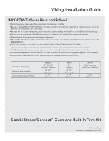
IMPORTANT–Please Read and Follow!
•
Before beginning, please read these instructions completely and carefully.
•
Be sure to DISCONNECT THE PLUG of the microwave oven from the electrical outlet before installing the built-in trim kit.
Remove the turntable from the oven cavity.
•
Because the kit includes metal parts, caution should be used in handling and installation to avoid the possibility of injury.
•
Do not remove permanently affixed labels, warnings, or plates from the product. This may void the warranty.
•
Please observe all local and national codes and ordinances.
• The installer should leave these instructions with the consumer who should retain for local inspector’s use and for
future reference.
•
This built-in trim kit is designed for use ONLY WITH VIKING COMBI STEAM/CONVECT™ OVEN.
•
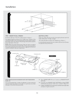
Your oven can be built into a cabinet or wall or above any electric wall oven, gas wall oven or warming drawer.
•
NOTE: The bottom of the cut-out opening for built-in use must be 36 inches (915 mm) or higher from the floor.
•
The electrical requirements for this oven are 120 volts, 15 amps. The oven has a 5-15 plug and requires a 5-15 receptacle.
•
PLEASE READ THESE INSTRUCTIONS THOROUGHLY BEFORE BEGINNING INSTALLATION!
HEIGHT
WIDTH
DEPTH
Cabinet or wall opening
19" - 19 1/8"
(482 mm - 486 mm)
28"
(712 mm)
23 1/4" minimum
(509.5 mm minimum)
Built-in kit frame assembly
22 1/8"
(562.1 mm)
29 1/2"
(749.3 mm)
Combi Steam/Convect™ Oven
17 1/4"
(438 mm)
21 3/4"
(553 mm)
18 3/8"
(468 mm)