Viking VCSO210SS Installation Instructions - Page 6
Step 5: Installation Of Rear Spacer And Exhaust Duct, Upper, Step 6: Installation Of Exhaust Duct
 |
View all Viking VCSO210SS manuals
Add to My Manuals
Save this manual to your list of manuals |
Page 6 highlights
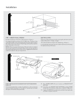
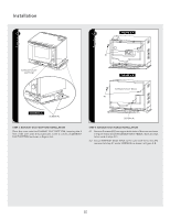
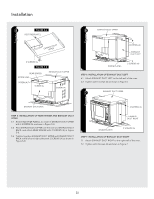
Installation 5 FIGURE 5-A RECTIFIER PLATE L EXHAUUPSPTEDRUCT 4 SCREWS (A) FIGURE 5-B REAR SPACER SCREW (A) EXHAUST DUCT UPPER SCREW (A) SCREW (A) SCREW (A) 6 EXHAUST DUCT UPPER 4 SCREWS (A) EXHAUST DUCT LEFT DIVIDE PLATE L 2 SCREWS (A) STEP 6: INSTALLATION OF EXHAUST DUCT LEFT 6.1 Attach EXHAUST DUCT LEFT to the left wall of the oven. 6.2 Tighten with 6 screws (A) as shown in Figure 6. 7 EXHAUST DUCT UPPER EXHAUST DUCT BACK 2 SCREWS (A) STEP 5: INSTALLATION OF REAR SPACER and EXHAUST DUCT UPPER 5.1 Attach RECTIFIER PLATE L to inside of EXHAUST DUCT UPPER with 4 SCREWS (A) as shown in Figure 5-A. 5.2 Place EXHAUST DUCT UPPER over the oven and EXHAUST DUCT BACK, and attach REAR SPACER with 2 SCREWS (A) in Figure 5-B. 5.3 Tighten together EXHAUST DUCT UPPER and EXHAUST DUCT BACK at the left and right sides with 2 SCREWS (A) as shown in Figure 5-B. EXHAUST DUCT RIGHT DIVIDE PLATE R 2 SCREWS (A) STEP 7: INSTALLATION OF EXHAUST DUCT RIGHT 7.1 Attach EXHAUST DUCT RIGHT to the right wall of the oven. 7.2 Tighten with 4 screws (A) as shown in Figure 7. E6
-
 1
1 -
 2
2 -
 3
3 -
 4
4 -
 5
5 -
 6
6 -
 7
7 -
 8
8
 |
 |
