Weider 130 English Manual - Page 5
Assembly
 |
View all Weider 130 manuals
Add to My Manuals
Save this manual to your list of manuals |
Page 5 highlights
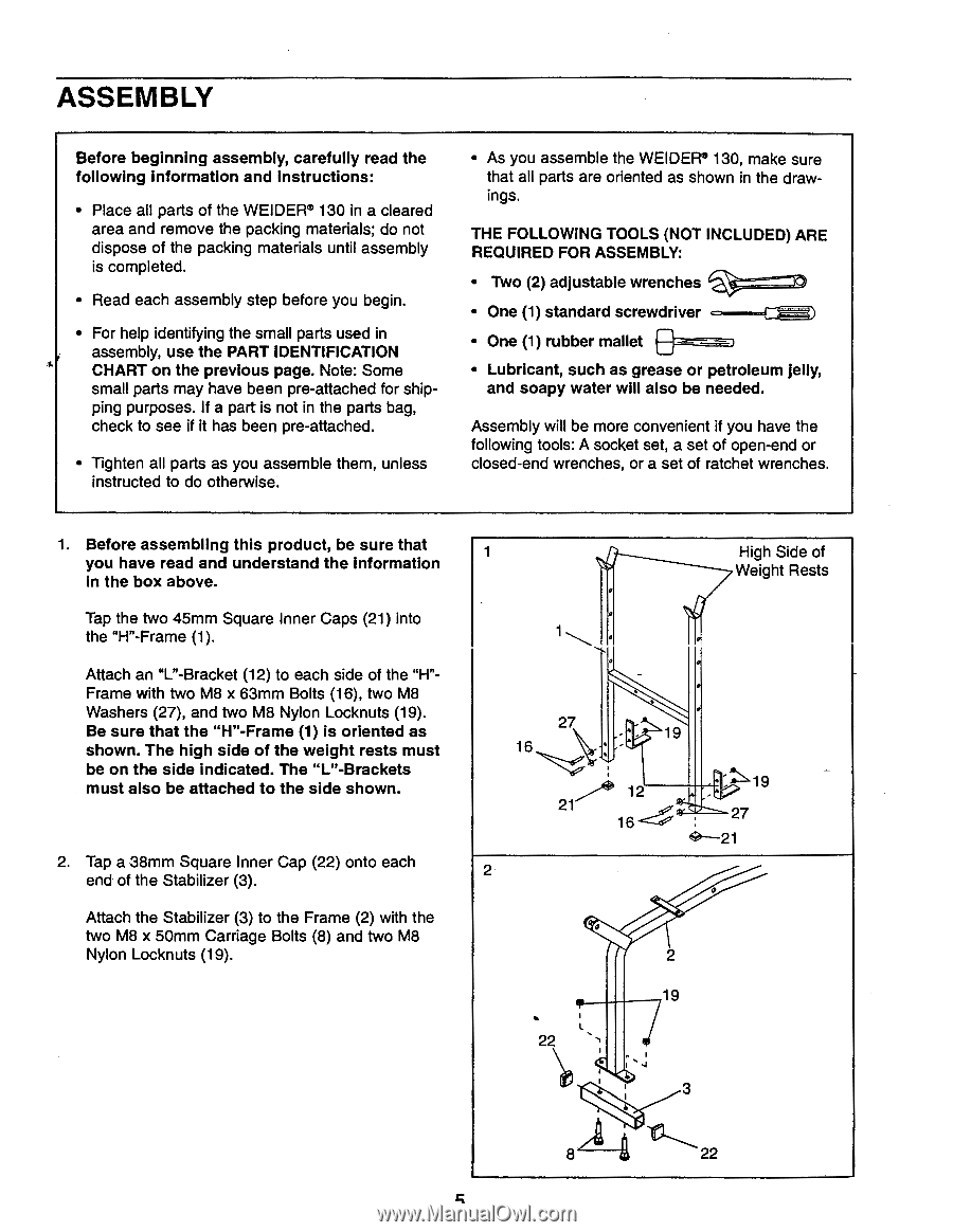
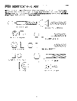
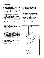
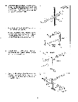
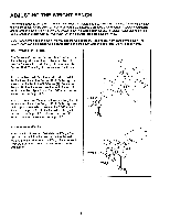
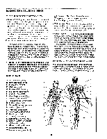
ASSEMBLY Before beginning assembly, carefully read the following information and instructions: • Place all parts of the WEIDER® 130 in a cleared area and remove the packing materials; do not dispose of the packing materials until assembly is completed. • Read each assembly step before you begin. • For help identifying the small parts used in assembly, use the PART IDENTIFICATION CHART on the previous page. Note: Some small parts may have been pre-attached for shipping purposes. If a part is not in the parts bag, check to see if it has been pre-attached. • Tighten all parts as you assemble them, unless instructed to do otherwise. • As you assemble the WEIDER® 130, make sure that all parts are oriented as shown in the drawings. THE FOLLOWING TOOLS (NOT INCLUDED) ARE REQUIRED FOR ASSEMBLY: • Two (2) adjustable wrenches €* -----"TI • One (1) standard screwdriver • One (1) rubber mallet • Lubricant, such as grease or petroleum jelly, and soapy water will also be needed. Assembly will be more convenient if you have the following tools: A socket set, a set of open-end or closed-end wrenches, or a set of ratchet wrenches. 1. Before assembling this product, be sure that you have read and understand the information in the box above. Tap the two 45mm Square Inner Caps (21) into the "H"-Frame (1). Attach an "L"-Bracket (12) to each side of the "H"Frame with two M8 x 63mm Bolts (16), two M8 Washers (27), and two M8 Nylon Locknuts (19). Be sure that the "H"-Frame (1) is oriented as shown. The high side of the weight rests must be on the side indicated. The "L"-Brackets must also be attached to the side shown. 2. Tap a 38mm Square Inner Cap (22) onto each end of the Stabilizer (3). Attach the Stabilizer (3) to the Frame (2) with the two M8 x 50mm Carriage Bolts (8) and two M8 Nylon Locknuts (19). 1 27 16 21 2 19 12 16 0 22 2 19 3 High Side of Weight Rests 27 8 22
-
 1
1 -
 2
2 -
 3
3 -
 4
4 -
 5
5 -
 6
6 -
 7
7 -
 8
8 -
 9
9 -
 10
10 -
 11
11 -
12
 |
 |