Weider 144 English Manual - Page 6
Assembly
 |
View all Weider 144 manuals
Add to My Manuals
Save this manual to your list of manuals |
Page 6 highlights
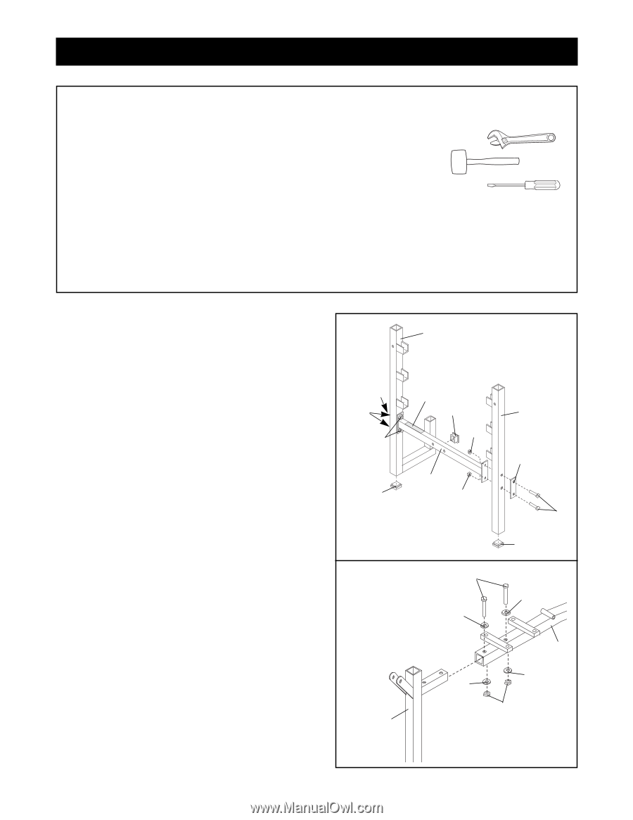
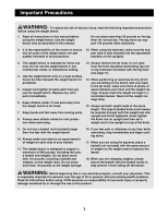
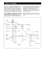
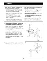
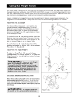
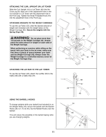
Assembly Before beginning assembly, carefully read the following information and instructions: ¥ Place all parts in a cleared area and remove the packing materials; do not dispose of the packing materials until assembly is completed. ¥ Tighten all parts as you assemble them, unless instructed to do otherwise. ¥ For help identifying the small parts used in assembly, use the PART IDENTIFICATION CHART on the page 5. ¥ As you assemble the weight bench, be sure that all parts are oriented as shown in the drawings. THE FOLLOWING TOOLS (NOT INCLUDED) ARE REQUIRED FOR ASSEMBLY: ¥ Two (2) adjustable wrenches ¥ One (1) rubber mallet ¥ One (1) standard screwdriver ¥ Lubricant, such as grease or petroleum jelly, and soapy water. Assembly will be more convenient if you have the following tools: A socket set, a set of open-end or closed-end wrenches or a set of ratchet wrenches. 1. Before assembling this product, make sure you understand the information in the box above. Press a 50mm x 50mm Square Inner Cap (36) into the lower end of each Upright (1, 15). Press a 45mm x 45mm Square Inner Cap (28) into the base of the Right Upright (1). Orient the Crossbar (3) with the warning decal facing up as shown. Attach the Crossbar to the Left Upright (15) with two M10 x 70mm Bolts (26), a Support Plate (14) and two M10 Nylon Locknuts (30). The Upright must be oriented as shown. Attach the Crossbar (3) to Right Upright (1) in the same manner. 1 14 26 30 36 1 Decal 28 30 3 30 15 14 26 2. Attach the Frame (2) to the welded bracket on the 2 Front Leg (8) with two M8 x 50mm Bolts (44), four M8 Washers (17), and two M8 Nylon Locknuts (34). 36 44 17 17 2 17 17 34 8 6
-
 1
1 -
 2
2 -
 3
3 -
 4
4 -
 5
5 -
 6
6 -
 7
7 -
 8
8 -
 9
9 -
 10
10 -
 11
11 -
 12
12 -
13
-
14
-
15
-
16
 |
 |