Weider 7400 Weight English Manual - Page 4
Assembly
 |
View all Weider 7400 Weight manuals
Add to My Manuals
Save this manual to your list of manuals |
Page 4 highlights
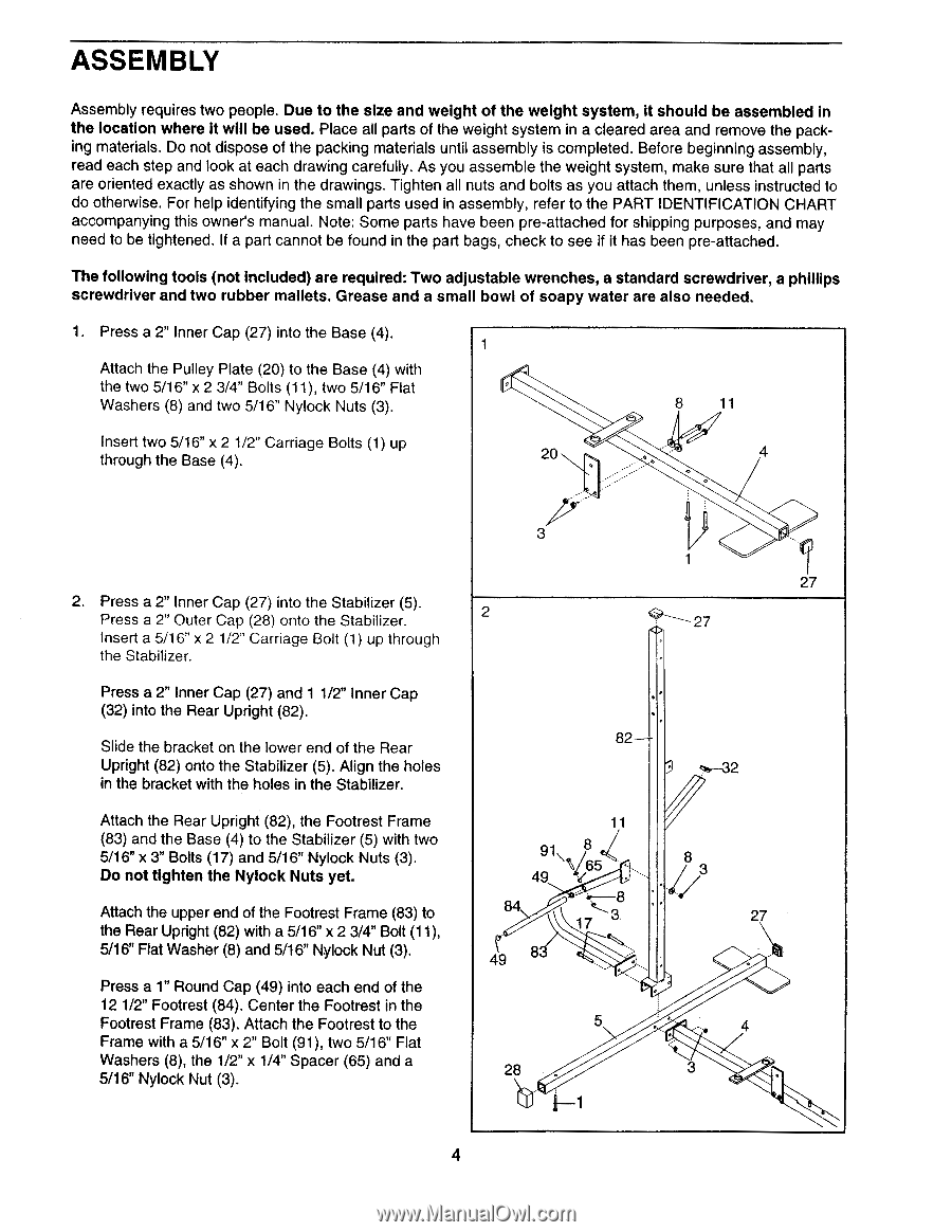
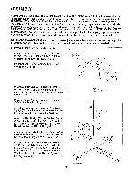
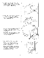
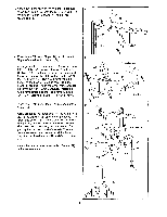
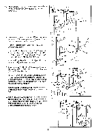
ASSEMBLY Assembly requires two people. Due to the size and weight of the weight system, it should be assembled in the location where it will be used. Place all parts of the weight system in a cleared area and remove the packing materials. Do not dispose of the packing materials until assembly is completed. Before beginning assembly, read each step and look at each drawing carefully. As you assemble the weight system, make sure that all parts are oriented exactly as shown in the drawings. Tighten all nuts and bolts as you attach them, unless instructed to do otherwise. For help identifying the small parts used in assembly, refer to the PART IDENTIFICATION CHART accompanying this owner's manual. Note: Some parts have been pre-attached for shipping purposes, and may need to be tightened. If a part cannot be found in the part bags, check to see if it has been pre-attached. The following tools (not included) are required: Two adjustable wrenches, a standard screwdriver, a phillips screwdriver and two rubber mallets. Grease and a small bowl of soapy water are also needed. 1. Press a 2" Inner Cap (27) into the Base (4). 1 Attach the Pulley Plate (20) to the Base (4) with the two 5/16" x 2 3/4" Bolts (11), two 5/16" Flat Washers (8) and two 5/16" Nylock Nuts (3). 8 11 Insert two 5/16" x 2 1/2" Carriage Bolts (1) up through the Base (4). 20 4 2. Press a 2" Inner Cap (27) into the Stabilizer (5). Press a 2" Outer Cap (28) onto the Stabilizer. Insert a 5/16" x 2 1/2" Carriage Bolt (1) up through the Stabilizer. Press a 2" Inner Cap (27) and 1 1/2" Inner Cap (32) into the Rear Upright (82). Slide the bracket on the lower end of the Rear Upright (82) onto the Stabilizer (5). Align the holes in the bracket with the holes in the Stabilizer. Attach the Rear Upright (82), the Footrest Frame (83) and the Base (4) to the Stabilizer (5) with two 5/16" x Bolts (17) and 5/16" Nylock Nuts (3). Do not tighten the Nylock Nuts yet. Attach the upper end of the Footrest Frame (83) to the Rear Upright (82) with a 5/16" x 2 3/4" Bolt (11), 5/16" Flat Washer (8) and 5/16" Nylock Nut (3). Press a 1" Round Cap (49) into each end of the 12 1/2" Footrest (84). Center the Footrest in the Footrest Frame (83). Attach the Footrest to the Frame with a 5/16" x 2" Bolt (91), two 5/16" Flat Washers (8), the 1/2" x 1/4" Spacer (65) and a 5/16" Nylock Nut (3). 3 2 1 27 27 82 t;t.--32 11 91\ ' 49 8 .(65 84 17 8 49 8 / 3 27 5 28 • 4 3 4
-
 1
1 -
 2
2 -
 3
3 -
 4
4 -
 5
5 -
 6
6 -
 7
7 -
 8
8 -
 9
9 -
 10
10 -
11
-
12
-
13
-
14
-
15
-
16
-
17
-
18
-
19
-
20
 |
 |