Weider 7400 Weight English Manual - Page 7
Press/Squat
 |
View all Weider 7400 Weight manuals
Add to My Manuals
Save this manual to your list of manuals |
Page 7 highlights
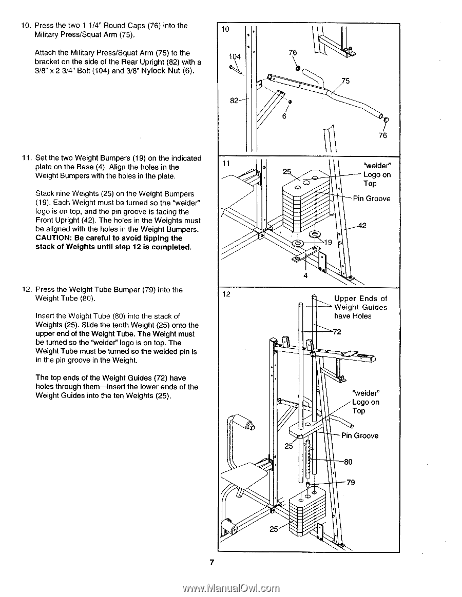
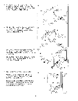
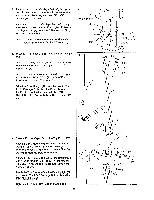
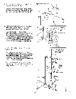
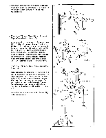
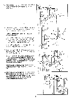
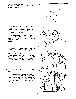
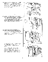
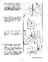
10. Press the two 1 1/4" Round Caps (76) into the Military Press/Squat Arm (75). Attach the Military Press/Squat Arm (75) to the bracket on the side of the Rear Upright (82) with a 3/8" x 2 3/4" Bolt (104) and 3/8" Nylock Nut (6). 10 104 82 11. Set the two Weight Bumpers (19) on the indicated plate on the Base (4). Align the holes in the 11 Weight Bumpers with the holes in the plate. Stack nine Weights (25) on the Weight Bumpers (19). Each Weight must be turned so the "welder" logo is on top, and the pin groove is facing the Front Upright (42). The holes in the Weights must be aligned with the holes in the Weight Bumpers. CAUTION: Be careful to avoid tipping the stack of Weights until step 12 is completed. 12. Press the Weight Tube Bumper (79) into the Weight Tube (80). 12 Insert the Weight Tube (80) into the stack of Weights (25). Slide the tenth Weight (25) onto the upper end of the Weight Tube. The Weight must be turned so the "weider" logo is on top. The Weight Tube must be turned so the welded pin is in the pin groove in the Weight. The top ends of the Weight Guides (72) have holes through them-insert the lower ends of the Weight Guides into the ten Weights (25). 76 75 6 76 25 ef) "weider" Logo on Top Pin Groove 42 19 4 Upper Ends of Weight Guides have Holes 72 25 o "welder" Logo on Top Pin Groove 80 79 0 25 7
-
 1
1 -
 2
2 -
 3
3 -
 4
4 -
 5
5 -
 6
6 -
 7
7 -
 8
8 -
 9
9 -
 10
10 -
 11
11 -
 12
12 -
13
-
14
-
15
-
16
-
17
-
18
-
19
-
20
 |
 |