Weider Club 16.8st English Manual - Page 6
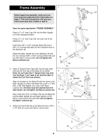
Frame Assembly - locations
 |
View all Weider Club 16.8st manuals
Add to My Manuals
Save this manual to your list of manuals |
Page 6 highlights
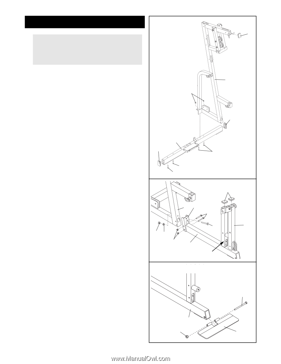
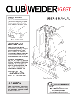
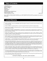
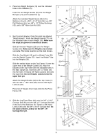
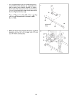
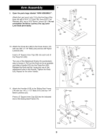
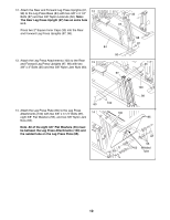
Frame Assembly 1 24 1. Before beginning assembly, make sure you have read and understood the information on page 5. This brief introduction will save you much more time than it takes to read it! Open the parts bag labeled ÒFRAME ASSEMBLY.Ó Press a 2Ó x 3Ó Inner Cap (24) into the Main Upright (3) in the indicated location. Press a 2Ó x 3Ó Inner Cap (24) into each end of the Stabilizer (5). Inset three 3/8Ó x 3 3/4Ó Carriage Bolts (52) and a 3/8Ó x 5Ó Carriage Bolt (82) into the indicated holes in the Stabilizer (5). Attach the Main Upright (3) to the Stabilizer (5) with the two indicated 3/8Ó x 3 3/4Ó Carriage Bolts (52) and two 3/8Ó Nylon Locknuts (50). Do not tighten the Nylon Locknuts yet. 2. Press 2Ó Square Inner Caps (33) into the Leg Lever (29) and the front leg on the Base (8) as shown. Note: Do not insert the 2Ó Square Inner Cap fully into the Base; it will need to be removed later to attach the Curl Post (not shown). Align the bracket on the Base (8) with the holes in the Main Upright (3). Attach the Base with a 3/8Ó x 4Ó Bolt (65), a 3/8Ó Flat Washer (55), and a 3/8Ó Nylon Locknut (50). The Bolt must be inserted from the side shown. Do not tighten the Nylon Locknut yet. Next, insert two 5/16Ó x 3Ó Bolts (78) into the Base (8) and the Main Upright (3) and finger tighten a 5/16Ó Nylon Locknut (81) onto each Bolt. Do not tighten the Nylon Locknuts yet. 3. Attach the Foot Plate (4) to the Base (8) with a 3/8Ó x 5 1/2Ó Bolt (57) and a 3/8Ó Nylon Locknut (50). 3 50 24 5 24 82 52 2 52 33 3 Bracket 78 65 29 50 55 81 8 Front Leg 3 57 8 50 4 6
-
 1
1 -
 2
2 -
 3
3 -
 4
4 -
 5
5 -
 6
6 -
 7
7 -
 8
8 -
 9
9 -
 10
10 -
 11
11 -
 12
12 -
13
-
14
-
15
-
16
-
17
-
18
-
19
-
20
-
21
-
22
-
23
-
24
-
25
-
26
-
27
-
28
-
29
-
30
-
31
-
32
-
33
 |
 |