Weider Club C670 Bench English Manual - Page 6
Assembly
 |
View all Weider Club C670 Bench manuals
Add to My Manuals
Save this manual to your list of manuals |
Page 6 highlights
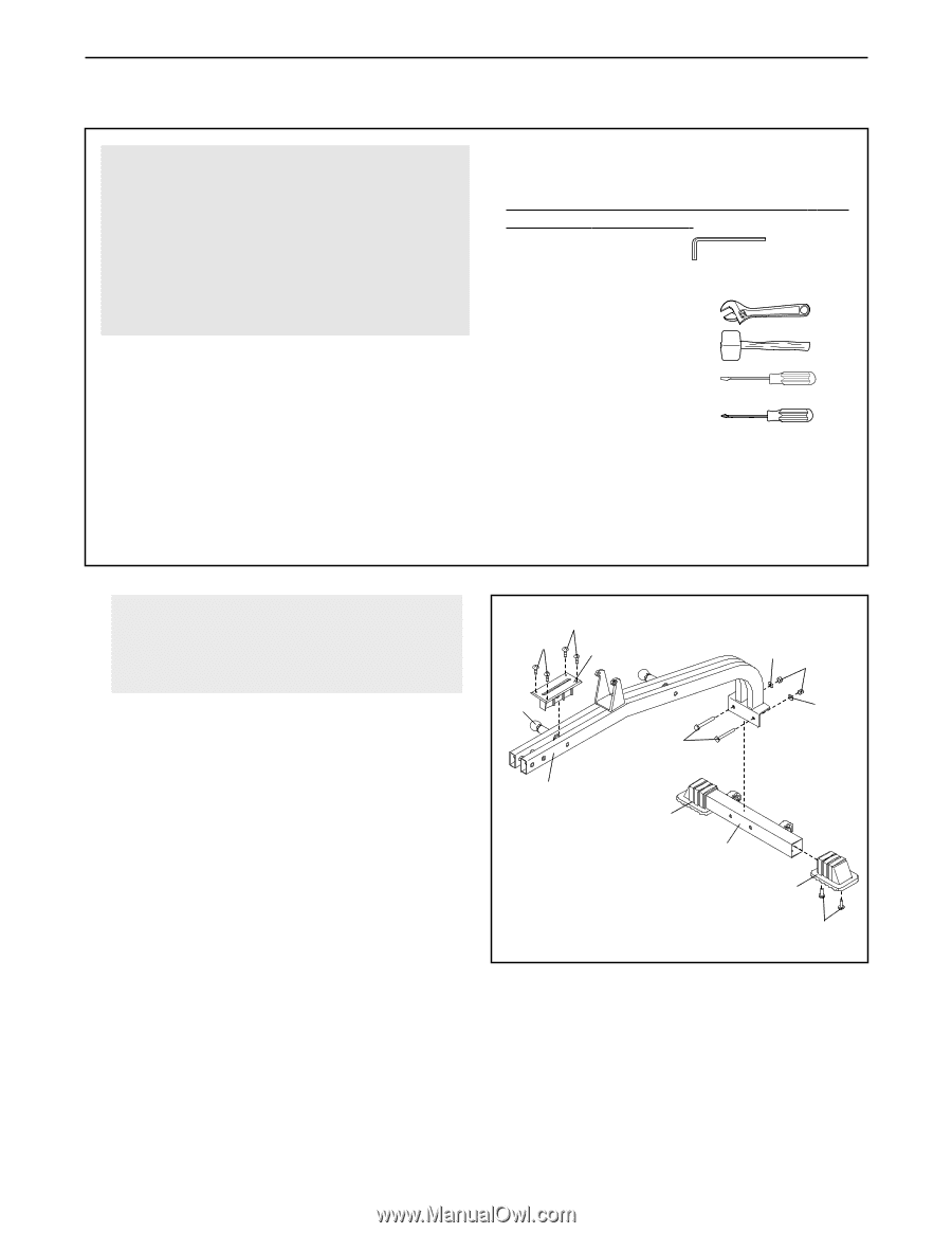
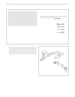
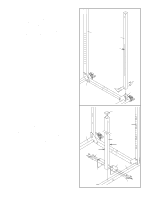
ASSEMBLY Make Things Easier for Yourself Everything in this manual is designed to ensure that the weight bench can be assembled successfully by anyone. However, it is important to realize that the versatile weight bench has many parts and that the assembly process will take time. Most people find that by setting aside plenty of time, assembly will go smoothly. Before beginning assembly, carefully read the following information and instructions: • Assembly requires two people. • Place all parts in a cleared area and remove the packing materials. Do not dispose of the packing materials until assembly is completed. • Tighten all parts as you assemble them, unless instructed to do otherwise. • As you assemble the weight bench, make sure all parts are oriented as shown in the drawings. • For help identifying small parts, use the PART IDENTIFICATION CHART. The included Allen wrench and the following tools (not included) are required for assembly: • Two adjustable wrenches • One rubber mallet • One standard screwdriver • One Phillips screwdriver • Lubricant, such as grease or petroleum jelly, and soapy water. Assembly will be more convenient if you have a socket set, a set of open-end or closed-end wrenches, or a set of ratchet wrenches. 1. Before beginning assembly, make sure you understand the information in the box above. For help identifying small parts, use the PART IDENTIFICATION CHART. Attach a Small Base Cap (20) to the Stabilizer (2) with two M4 x 16mm Screws (36). Attach another Small Base Cap in the same manner. Pull the Small Adjustment Knob (23) out and slide the Seat Bracket Sleeve (93) between the tubes in the Bench Frame (1) as shown. Engage the Knob into the Sleeve and Bench Frame. Attach the Sleeve to the Bench Frame with four M4 x 16mm Screws (36). Attach the Bench Frame (1) to the Stabilizer (2) with two M10 x 65mm Bolts (100), two M10 Washers (35), and two M10 Nylon Locknuts (34). Do not tighten the Locknuts yet. 1 36 36 93 23 1 35 34 35 100 20 2 20 36 6
-
 1
1 -
 2
2 -
 3
3 -
 4
4 -
 5
5 -
 6
6 -
 7
7 -
 8
8 -
 9
9 -
 10
10 -
 11
11 -
 12
12 -
13
-
14
-
15
-
16
-
17
-
18
-
19
-
20
-
21
-
22
-
23
-
24
-
25
-
26
-
27
-
28
-
29
-
30
-
31
-
32
-
33
-
34
 |
 |