Weider Flex 225 Owners Manual - Page 7
assembling
 |
View all Weider Flex 225 manuals
Add to My Manuals
Save this manual to your list of manuals |
Page 7 highlights
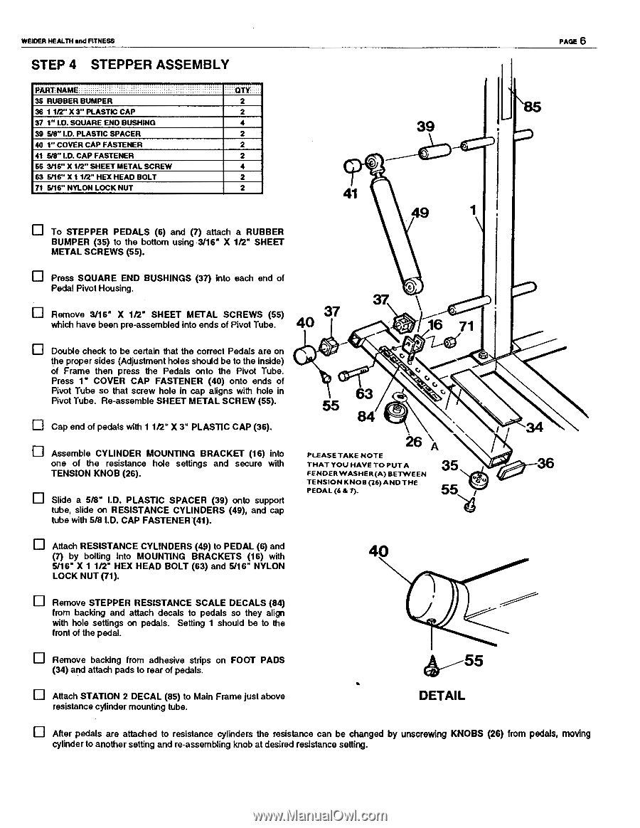
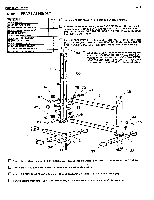
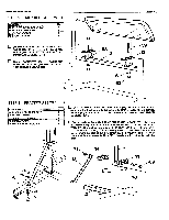
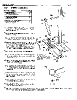
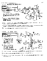
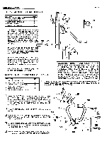
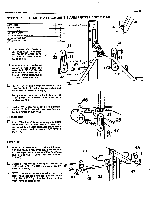
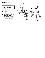
WEIDER HEALTH and FITNESS STEP 4 STEPPER ASSEMBLY _. . . PART NAME 35 RUBBER BUMPER 36 1 1/2" X 3" PLASTIC CAP 37 1" I.D. SQUARE END BUSHING 39 5/8" I.D. PLASTIC SPACER 40 1" COVER CAP FASTENER 41 5/8" I.D. CAP FASTENER 55 3/16" X 1/2" SHEET METAL SCREW 63 5/16" X 1 1/2" HEX HEAD BOLT 71 5/16" NYLON LOCK NUT QTY 2 2 4 2 2 2 4 2 2 To STEPPER PEDALS (6) and (7) attach a RUBBER BUMPER (35) to the bottom using 3/16" X 112" SHEET METAL SCREWS (55). 39 41 49 PAGE 6 Press SQUARE END BUSHINGS (37) into each end of Pedal Pivot Housing. Remove 3/16" X 1/2" SHEET METAL SCREWS (55) which have been pre-assembled into ends of Pivot Tube. Double check to be certain that the correct Pedals are on the proper sides (Adjustment holes should be to the inside) of Frame then press the Pedals onto the Pivot Tube. Press 1" COVER CAP FASTENER (40) onto ends of Pivot Tube so that screw hole in cap aligns with hole in Pivot Tube. Re-assemble SHEET METAL SCREW (55). Cap end of pedals with 1 1t2" X 3" PLASTIC CAP (36). Assemble CYLINDER MOUNTING BRACKET (16) into one of the resistance hole settings and secure with TENSION KNOB (26). Slide a 5/8" I.D. PLASTIC SPACER (39) onto support tube, slide on RESISTANCE CYLINDERS (49), and cap tube with 5/8 I.D. CAP FASTENER (41). 37 40 37 \ 16 71 2411:.( 63 55 84 26 \A PLEASE TAKE NOTE THAT YOU HAVE TO PUT A FENDER WASHER(A)BETWEEN TENSION KNOB (26)AND THE PEDAL (6 & 7). 35 5%1 Attach RESISTANCE CYLINDERS (49) to PEDAL (6) and (7) by bolting into MOUNTING BRACKETS (16) with 5/16` X 1 1/2" HEX HEAD BOLT (63) and 5/16" NYLON LOCK NUT (71). 40 Remove STEPPER RESISTANCE SCALE DECALS (84) from backing and attach decals to pedals so they align with hole settings on pedals. Setting 1 should be to the front of the pedal. Remove backing from adhesive strips on FOOT PADS (34) and attach pads to rear of pedals. Attach STATION 2 DECAL (85) to Main Frame just above resistance cylinder mounting tube. 04. 55 DETAIL 0 After pedals are attached to resistance cylinders the resistance can be changed by unscrewing KNOBS (26) from pedals, moving cylinder to another setting and re-assembling knob at desired resistance setting.
-
 1
1 -
 2
2 -
 3
3 -
 4
4 -
 5
5 -
 6
6 -
 7
7 -
 8
8 -
 9
9 -
 10
10 -
 11
11 -
 12
12
 |
 |