Weider Flex 225 Owners Manual - Page 9
tljtjtH, HANDLE, ASStililliLA, SELECTING, PROPER, RESISTANCE
 |
View all Weider Flex 225 manuals
Add to My Manuals
Save this manual to your list of manuals |
Page 9 highlights
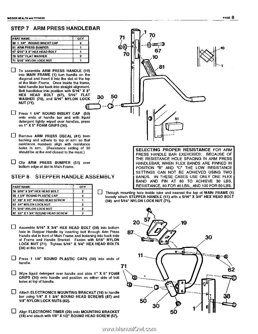
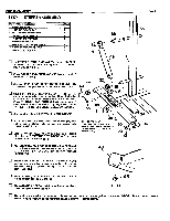
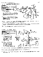
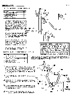
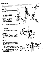
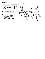
WEIDER HEALTH and FITNESS STEP 7 ARM PRESS HANDLEBAR PART NAME 50 1 1/4" ROUND INSERT CAP 51 ARM PRESS BUMPER 67 5/16" X 3" HEX HEAD BOLT 70 5/16" FLAT WASHER 71 5/16" NYLON LOCK NUT OTY 2 1 1 2 1 To assemble ARM PRESS HANDLE (10) into MAIN FRAME (1) turn handle on the diagonal and insert it into the slot at the top of the Main Frame. Once inside the frame, twist handle bar back into straight alignment. Bolt handlebar into position with 5/16" X 3" HEX HEAD BOLT (67), 5/16" FLAT WASHER (70), and 5/16" NYLON LOCK 0 NUT (71). 71 1 70 I o'p-- '-1 67 7O J 10 81 50 PAGE 8 Press 1 1/4" ROUND INSERT CAP (50) onto ends of handle bar and with liquid 51 detergent lightly wiped over handles, press on 1" X 5" FOAM GRIPS (30). Remove ARM PRESS DECAL (81) from backing and adhere to top of arm so that resistance numbers align with resistance holes in arm. (Resistance setting of 30 should be at the end closest to the mast.) SELECTING PROPER RESISTANCE FOR ARM PRESS HANDLE BAR EXERCISES: . BECAUSE OF Clip ARM PRESS BUMPER (51) over bottom edge of slot in Main Frame. THE RESISTANCE HOLE SPACING IN ARM PRESS HANDLEBAR, WHEN FLEX BANDS ARE PINNED IN POSITION "B" AND "C" THE LOW RESISTANCE STEP 8 S I tljtjtH HANDLE ASStililliLA SETTINGS CAN NOT BE ACHIEVED USING TWO BANDS. IN THESE CASES USE ONLY ONE FLEX BAND AND PIN AT 60 TO ACHIEVE 30 LBS. PART NAME WY RESISTANCE, 80 FOR 40 LBS., AND 100 FOR 50 LBS. 38 5/16" X 3/V HEX HEAD BOLT 50 11/4" ROUND PLASTIC CAP 57 1/8" X 1/2" ROUND HEAD SCREW 62 1/4" NYLON LOCK NUT 2 El Through mounting hole inside tube and nearest the top of MAIN FRAME (1) 2 loosely attach STEPPER HANDLE (11) with a 5/16" X 3/4" HEX HEAD BOLT I (38) and 5/16" NYLON LOCK NUT (71). 2 71 5/16" NYLON LOCK NUT 2 87 1/4" X 1 3/4" ROUND HEAD SCREW 2 Assemble 5/16" X 3/4" HEX HEAD BOLT (38) into bottom hole in Stepper Handle by insetting bolt through Arm Press Handle slot in front of Main Frame and fastening into back side of Frame and Handle Bracket. Fasten with 5/16" NYLON LOCK NUT (71). Tighten 5/16" X 3/4" HEX HEAD BOLTS (38) at this time. 20 87 7 - 7r 19 V • 447 \ 11 Press 1 1/4" ROUND PLASTIC CAPS (50) into ends of handle. 71 30 n2 Wipe liquid detergent over handle and slide 1" X 5" FOAM GRIPS (30) onto handle and position on either side of bolt holes at top of handle. Attach ELECTRONICS MOUNTING BRACKET (19) to handle bar using 1/4" X 1 3/4" ROUND HEAD SCREWS (87) and 1/4" NYLON LOCK NUTS (62). Align ELECTRONIC TIMER (20) onto MOUNTING BRACKET (19) and attach with 1/8" X 1/2" ROUND HEAD SCREW (57). 50 30 50
-
 1
1 -
2
-
3
-
 4
4 -
 5
5 -
 6
6 -
 7
7 -
 8
8 -
 9
9 -
 10
10 -
 11
11 -
 12
12
 |
 |