Weider Platinum Plus 1000 English Manual - Page 7
the 90mm Thin Pulley 88 and Cable Trap 78
 |
View all Weider Platinum Plus 1000 manuals
Add to My Manuals
Save this manual to your list of manuals |
Page 7 highlights
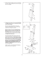
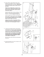
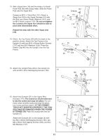
2. Insert two M10 x 65mm Carriage Bolts (103) up through the Base (1). Place a piece of tape over the Bolt heads to hold them in place. Connect the Upright Base (2) to the Base with the two Carriage Bolts and two M10 Nylon Locknuts (112). Do not tighten these Locknuts yet. Connect the Upright Base (2) to the Base (1) with two M10 x 67mm Bolts (111) and two M10 Nylon Locknuts (112). Fully tighten these Locknuts. Set the Mech Frame (124) onto the Base (1) behind the Upright Base. Handtighten two M10 x 73mm Bolts (137) and two M10 Washers (129) into the indicated holes in the Base and Mech Frame. Note: The Mech Frame will not be shown in the following drawings for clarity. Note: One end of the Rope (70) is connected to the Right Arm Frame (171). Untie the loose end of the Rope and route it through the Upright Base (2). Make sure the Rope is still between the 90mm Thin Pulley (88) and Cable Trap (78) (see the inset drawing), and that the loose end of the Rope crosses under the connected end of the Rope. Insert two M14 x 155mm Bolts (107) through the Right Arm Frame (171) and the Upright Base (2). Hand tighten two M14 Nylon Locknuts (127) onto the Bolts. 3. Route the loose end of the Rope (70) through the Left Arm Frame (8) and a Swivel Arm (29). Make sure the Rope is under the indicated rod in the Swivel Arm. Attach the Swivel Arm (29) to the Left Arm Frame (8) with an M4 x 5mm Self-tapping Screw (176). Attach a "V"-pulley (93) inside the Swivel Arm (29) with an M10 x 53mm Button Bolt (140) and an M10 Nylon Locknut (112). 4. Route the loose end of the Rope (70) through a Rope Cover (169) and a Link (167) as shown. Make sure the large hole in the Rope Cover is on the side shown. Secure the set of Rope Clamps (165, 166) on the Rope with two M5 x 16mm Button Screws (164). Make sure that Rope is in the grooves of the Rope Clamps, that there is 1/2" between the Link and the Rope Clamps, and that the two Screws are fully tightened. Slide the Rope Cover over the Rope Clamps. 2 107 2 171 107 112 137 111 129 127 70 127 124 112 111 103 3 137 129 1 78 88 70 8 176 29 112 2 Rod 140 70 93 4 164 70 169 165 Large 167 Hole 166 7
-
 1
1 -
 2
2 -
 3
3 -
 4
4 -
 5
5 -
 6
6 -
 7
7 -
 8
8 -
 9
9 -
 10
10 -
 11
11 -
 12
12 -
13
-
14
-
15
-
16
-
17
-
18
-
19
-
20
-
21
-
22
-
23
-
24
-
25
-
26
-
27
-
28
-
29
-
30
-
31
-
32
-
33
-
34
 |
 |
