Weider Platinum Xp800 Canadian English Manual - Page 7
Sole May Be Damaged When The Power
 |
View all Weider Platinum Xp800 manuals
Add to My Manuals
Save this manual to your list of manuals |
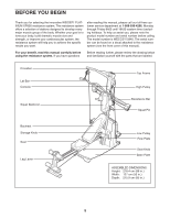
Page 7 highlights
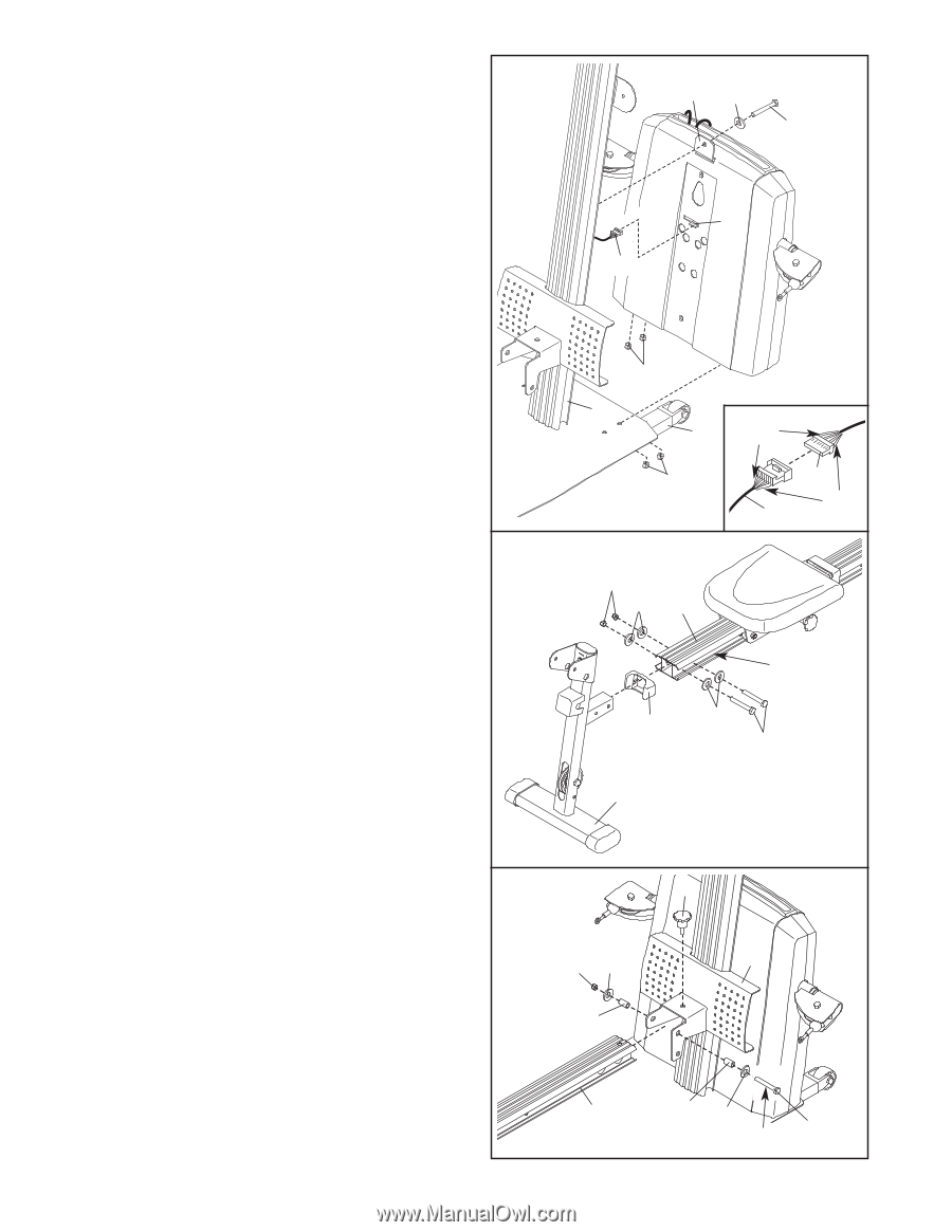
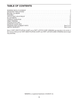
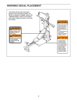
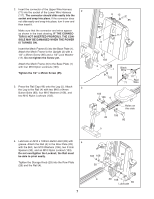
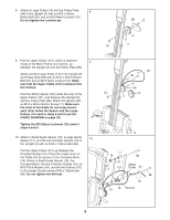
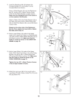
2. Insert the connector of the Upper Wire Harness (71) into the socket of the Lower Wire Harness 2 (117). The connector should slide easily into the socket and snap into place. If the connector does not slide easily and snap into place, turn it over and then insert it. Make sure that the connector and wires appear as shown in the inset drawing. IF THE CONNECTOR IS NOT INSERTED PROPERLY, THE CONSOLE MAY BE DAMAGED WHEN THE POWER IS TURNED ON. Insert the Mech Frame (6) into the Base Plate (1). Attach the Mech Frame to the Upright (2) with a 1/2" x 25mm Screw (85) and a 1/2" Lock Washer (12). Do not tighten the Screw yet. Attach the Mech Frame (6) to the Base Plate (1) with four M10 Nylon Locknuts (103). Tighten the 1/2" x 25mm Screw (85). 3. Press the Rail Cap (49) onto the Leg (5). Attach 3 the Leg to the Rail (4) with two M10 x 64mm Button Bolts (80), four M10 Washers (106), and two M10 Nylon Locknuts (103). 6 12 85 117 71 103 2 1 103 Black Wire 117 Red 71 Wire 103 106 4 Holes on this side 106 49 80 5 4. Lubricate an M10 x 125mm Button Bolt (89) with 4 grease. Attach the Rail (4) to the Row Plate (28) with the Bolt, two M10 Washers (106), two 31mm Spacers (30), and an M10 Nylon Locknut (103). Do not overtighten the Locknut; the Rail must be able to pivot easily. Tighten the Storage Knob (29) into the Row Plate (28) and the Rail (4). 103 106 30 29 28 4 30 106 89 Lubricate 7
-
 1
1 -
 2
2 -
 3
3 -
 4
4 -
 5
5 -
 6
6 -
 7
7 -
 8
8 -
 9
9 -
 10
10 -
 11
11 -
 12
12 -
13
-
14
-
15
-
16
-
17
-
18
-
19
-
20
-
21
-
22
-
23
-
24
-
25
-
26
-
27
 |
 |