Weider Power Guide X2 User Manual - Page 4
Cable Diagrams, Assembly
 |
View all Weider Power Guide X2 manuals
Add to My Manuals
Save this manual to your list of manuals |
Page 4 highlights
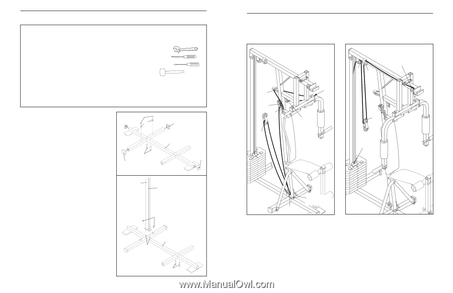
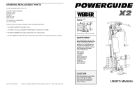
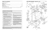
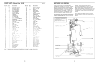
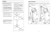
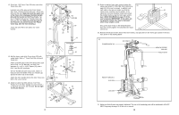
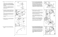
ASSEMBLY Before beginning assembly, carefully read the following information and instructions: • Place all parts of the POWERGUIDE X2 in a cleared area and remove the packing materials; do not dispose of the packing materials until assembly is completed. • For help identifying the small parts used in assembly, use the PART IDENTIFICATION CHART located in the centre of this manual. Note: Some small parts may have been preattached for shipping. If a part is not in the parts bag, check to see if it has been pre-attached. • During assembly, be sure that all parts are oriented as shown in the drawings. • Tighten all parts as you assemble them, unless instructed to do otherwise. The following tools (not included) are required: • Two (2) adjustable wrenches • One (1) phillips screwdriver • One (1) standard screwdriver • One (1) rubber mallet • Lubricant, such as grease or petroleum jelly, and soapy water will also be needed. Assembly will be more convenient if you have the following tools: A socket set, a set of open-end or closed-end wrenches, or a set of ratchet wrenches. 1. Press two 2" Outer Caps (37) onto the Base (38) in the indicated locations. Insert two 2" Inner Caps (36) into the ends of the Base. Attach the two Weight Bumpers (40) to the Base (38) with the two 1 1/4" Tap Screws (39). Insert two 5/16" x 2 1/2" Carriage Bolts (35) up through the indicated holes in the Base (38). 1 36 37 39 40 35 37 38 36 2. Attach the Guide Tube (34) to the two 5/16" x 2 2 1/2" Carriage Bolts (35) in the Base (38) with two 5/16" Nylon Locknuts (1). Be sure that the Guide Tube is turned so the slot is on the side shown. Insert two 5/16" x 2 1/2" Carriage Bolts (35) up through the indicated holes in the Base (38). 34 Slot 1 38 35 35 4 CABLE DIAGRAMS The diagrams below show the proper routing of the Low Cable (70) and the High Cable (71). Use the diagrams to make sure that the two cables are assembled correctly. The numbers show the routing of the Cables from the starting to ending points. LOW CABLE (70) HIGH CABLE (71) 2 4 5-High Pulley Station 6 4 5 2 7 8-Bracket 3 1-Weight Stack 1-Low Pulley Station 3 17
-
 1
1 -
 2
2 -
 3
3 -
 4
4 -
 5
5 -
 6
6 -
 7
7 -
 8
8 -
 9
9 -
 10
10 -
11
-
12
 |
 |