Weider Power Guide X2 User Manual - Page 6
Attaching The Lat Bar Or Nylon Strap
 |
View all Weider Power Guide X2 manuals
Add to My Manuals
Save this manual to your list of manuals |
Page 6 highlights
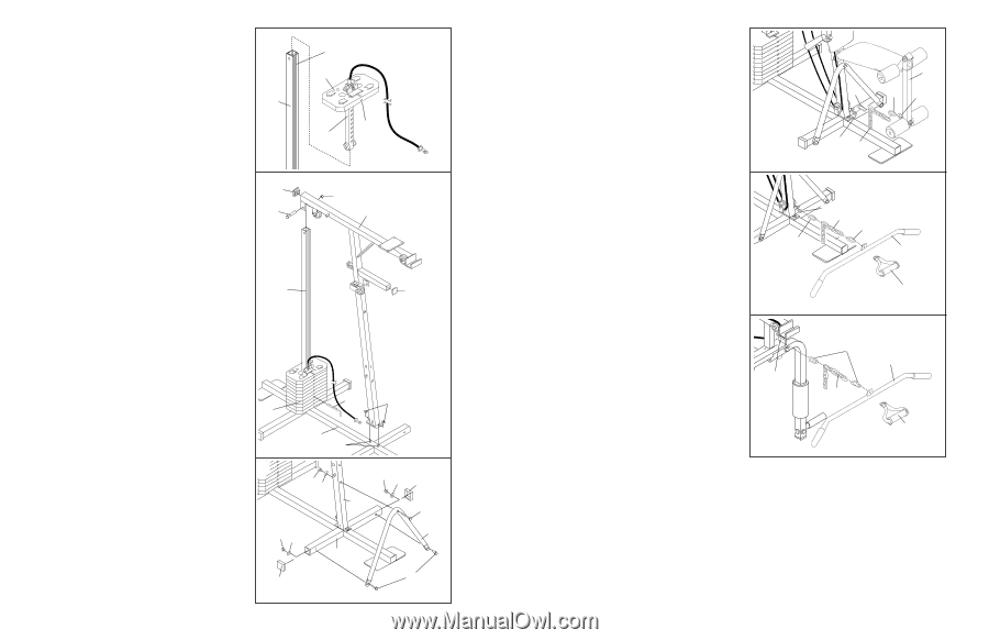
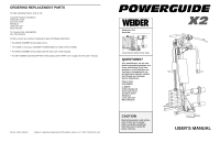
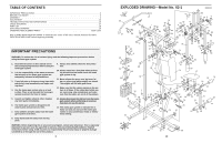
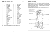
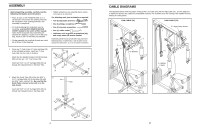
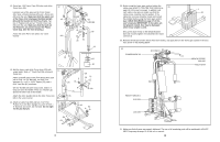
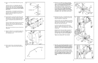
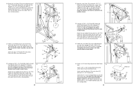
6. Slide the Weight Selector (47) and the Weight 6 (45) onto the Guide Tube (34). 34 Slot 45 Pin 47 Groove 7. Press a 2" Inner Cap (36) into the upper end of the Main Upright (41). Press a 1 1/2" Inner Cap (19) into the indicated location on the Main Upright. Attach the Main Upright (41) to the two 5/16" x 2 1/2" Carriage Bolts (35) in the Base (38) with two 5/16" Nylon Locknuts (1). Attach the Main Upright (41) to the Guide Tube (34) with a 5/16" x 2 3/4" Bolt (7) and a 5/16" Nylon Locknut (1). Insert the 4" Weight Pin (50) under the seventh Weight (45). 7 36 7 34 1 41 19 8. Attach the "V" Brace (42) to the Main Upright (41) with the 5/16" x 3 1/4" Bolt (43), a 5/16" Flat Washer (5), and a 5/16" Nylon Locknut (1). Do not tighten the Nylon Locknut yet. Attach the "V" Brace (42) to the Base (38) with two 5/16" x 3/4" Bolts (76), two 5/16" Flat Washers (5), and two 5/16" Nylon Locknuts (1). Make sure that the Washers and Nylon Locknuts are attached inside the Base. Tighten all Nylon Locknuts used in this step. Press two 2" Outer Caps (37) onto the Base (38). 50 45 38 35 8 1 5 41 15 38 37 1 1 5 37 43 42 76 6 ATTACHING THE LEG LEVER TO THE LOW PULLEY STATION To use the Leg Lever (20), the seat must be attached to the front upright (see ATTACHING AND REMOVING THE SEAT on page 14). Attach the Chain (58) between the Low Cable (70) and the 5/16" x 2" Eye Bolt (21) with two Cable Clips (57). ATTACHING THE LAT BAR OR NYLON STRAP TO THE LOW PULLEY STATION Attach the Lat Bar (60) to the Low Cable (70) with a Cable Clip (57). For some exercises, the Chain (58) should be attached between the Lat Bar and the Long Cable with two Cable Clips. Adjust the length of the Chain between the Lat Bar and the Low Cable so the Lat Bar is in the correct starting position for the exercise to be performed. The Nylon Strap (59) can be attached in the same manner. ATTACHING THE LAT BAR OR NYLON STRAP TO THE HIGH PULLEY STATION Attach the Lat Bar (60) to the High Cable (71) with a Cable Clip (57). For some exercises, the Chain (58) should be attached between the Lat Bar and the High Cable with two Cable Clips. Adjust the length of the Chain between the Lat Bar and the High Cable so the Lat Bar is in the correct starting position for the exercise to be performed. The Nylon Strap (59) can be attached in the same manner. 20 57 57 21 70 58 70 58 57 57 60 59 57 60 71 58 59 15
-
 1
1 -
 2
2 -
 3
3 -
 4
4 -
 5
5 -
 6
6 -
 7
7 -
 8
8 -
 9
9 -
 10
10 -
 11
11 -
 12
12
 |
 |