Weider Power Guide X2 User Manual - Page 5
Trouble-shooting And Maintenance
 |
View all Weider Power Guide X2 manuals
Add to My Manuals
Save this manual to your list of manuals |
Page 5 highlights
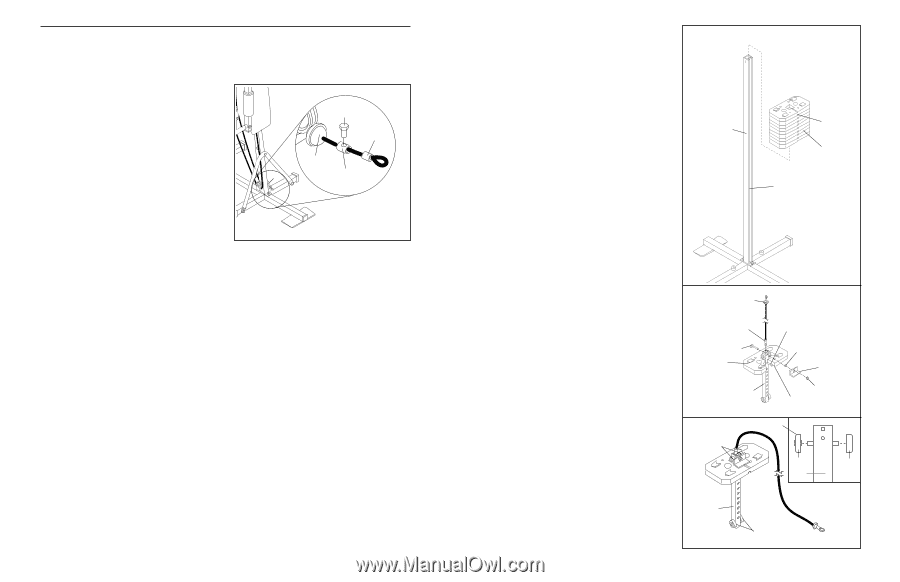
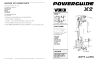
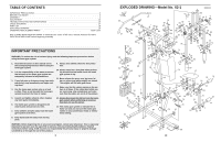
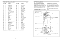
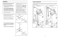
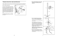
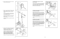
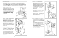
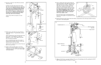
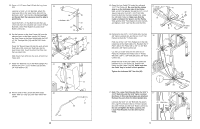
TROUBLE-SHOOTING AND MAINTENANCE Inspect and tighten all parts each time you use the home gym system. Replace any worn parts immediately. The home gym system can be cleaned using a damp cloth and mild non-abrasive detergent. Do not use solvents. HOW TO TIGHTEN THE CABLES Woven cable, the type of cable used on the home gym system, can stretch slightly when it is first used. If there is slack in the cables before resistance is felt, the cables should be tightened. Locate the adjustment sleeve and adjustment screw near the lower end of the Low Cable (70). Loosen the adjustment screw. Pull the end of the Low Cable until there is no slack. Slide the adjustment sleeve and the ball against the indicated 3 1/2" Thin Pulley (4). Retighten the adjustment screw. Make sure that the cables are not too tight, or the top weight will be lifted off the weight stack. Adjustment Screw 70 Ball 4 Adjustment Sleeve If the cables need to be replaced, see ORDERING REPLACEMENT PARTS on the back cover of this user's manual. 16 3. Slide nine Weights (45) onto the Guide Tube (34). 3 Make sure that the Weights are turned so the pin grooves are on the slotted side of the Guide Tube. Pin 34 Groove 45 Slot 4. Slide the tenth Weight (45) onto the Weight Selector (47). Make sure that the pin groove is resting on the pin on the Weight Selector. 4 Rubber Stop Find the High Cable (71) (see the PART IDENTIFICATION CHART). 71 Pin Hold the indicated end of the High Cable (71) inside the Weight Selector (47). Insert the 5/16" x 2" Carriage Bolt (64) into the Weight Selector and through the eyelet on the end of the High Cable. Slide the 1/2" x 7/16" Spacer (63) and the Weight Bracket (62) onto the Carriage Bolt. Thread a 5/16" Nylon Locknut (1) onto the Carriage Bolt. Do not tighten the Nylon Locknut yet. 5 IMPORTANT NOTE: The cables will need to be adjusted after assembly is completed. This will be performed in step 29. 64 45 47 63 62 1 Pin Groove Round Edge 46 5. Make sure that the four Nylon Wheels (46) are attached to the Weight Selector (47). In addition, make sure that each Nylon Wheel is turned so the round edge is away from the Weight Selector (see the inset drawing). 47 46 46 47 46 5
-
 1
1 -
 2
2 -
 3
3 -
 4
4 -
 5
5 -
 6
6 -
 7
7 -
 8
8 -
 9
9 -
 10
10 -
 11
11 -
12
 |
 |