Weider Pro 305 English Manual - Page 6
Stabilizer
 |
View all Weider Pro 305 manuals
Add to My Manuals
Save this manual to your list of manuals |
Page 6 highlights
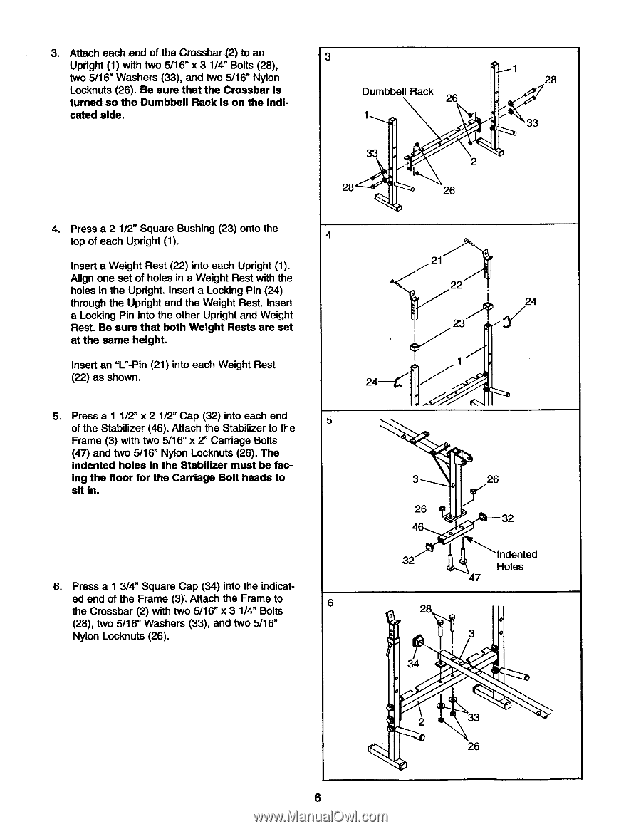
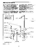
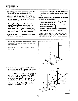
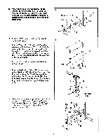
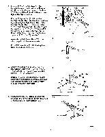
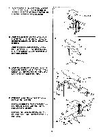
3. Attach each end of the. Crossbar (2) to an Upright (1) with two 5/16" x 3 1/4" Bolts (28), two 5/16" Washers (33), and two 5/16" Nylon Locknuts (26). Be sure that the Crossbar is turned so the Dumbbell Rack is on the indicated side. 3 Dumbbell Rack 26 1 33 28 2 26 1 28 33 4. Press a 2 1/2" Square Bushing (23) onto the top of each Upright (1). 4 Insert a Weight Rest (22) into each Upright (1). Align one set of holes in a Weight Rest with the holes in the Upright. Insert a Locking Pin (24) through the Upright and the Weight Rest. Insert a Locking Pin into the other Upright and Weight Rest. Be sure that both Weight Rests are set at the same height. Insert an "L"-Pin (21) into each Weight Rest (22) as shown. 5. Press a 1 1/2" x 2 1/2" Cap (32) into each end 5 of the Stabilizer (46). Attach the Stabilizer to the Frame (3) with two 5/16" x 2" Carriage Bolts (47) and two 5/16" Nylon Locknuts (26). The indented holes in the Stabilizer must be fac- ing the floor for the Carriage Bolt heads to sit in. 6. Press a 1 3/4" Square Cap (34) into the indicat- ed end of the Frame (3). Attach the Frame to 6 the Crossbar (2) with two 5/16" x 3 1/4" Bolts (28), two 5/16" Washers (33), and two 5/16" Nylon Locknuts (26). . 21 . 22 24 it 23 -3 / 1 24 3 26 46 32 0 28 26 32 Indented Holes 47 0 3 0 0 2 33 26 6
-
 1
1 -
 2
2 -
 3
3 -
 4
4 -
 5
5 -
 6
6 -
 7
7 -
 8
8 -
 9
9 -
 10
10 -
 11
11 -
 12
12 -
13
-
14
-
15
-
16
-
17
-
18
-
19
 |
 |