Weider Pro 305 English Manual - Page 9
Weider Pro 305 Manual
 |
View all Weider Pro 305 manuals
Add to My Manuals
Save this manual to your list of manuals |
Page 9 highlights
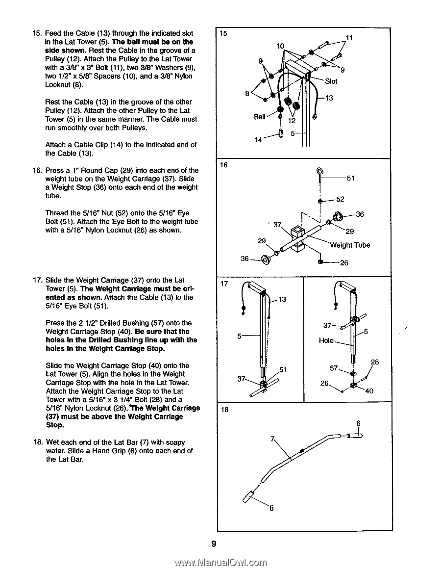
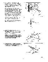
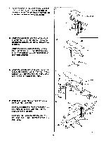
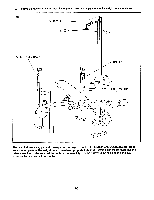
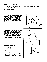
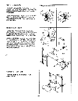
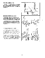
15. Feed the Cable (13) through the indicated slot in the Lat Tower (5). The ball must be on the side shown. Rest the Cable in the groove of a Pulley (12). Attach the Pulley to the Lat Tower with a 3/8" x 3" Bolt (11), two 3/8" Washers (9), two 1/2" x 5/8" Spacers (10), and a 3/8" Nylon Locknut (8). Rest the Cable (13) in the groove of the other Pulley (12). Attach the other Pulley to the Lat Tower (5) in the same manner. The Cable must run smoothly over both Pulleys. Attach a Cable Clip (14) to the indicated end of the Cable (13). 16. Press a 1" Round Cap (29) into each end of the weight tube on the Weight Carriage (37). Slide a Weight Stop (36) onto each end of the weight tube. Thread the 5/16" Nut (52) onto the 5/16" Eye Bolt (51). Attach the Eye Bolt to the weight tube with a 5/16" Nylon Locknut (26) as shown. 17. Slide the Weight Carriage (37) onto the Lat Tower (5). The Weight Carriage must be oriented as shown. Attach the Cable (13) to the 5/16" Eye Bolt (51). Press the 2 1/2" Drilled Bushing (57) onto the Weight Carriage Stop (40). Be sure that the holes in the Drilled Bushing line up with the holes in the Weight Carriage Stop. Slide the Weight Carriage Stop (40) onto the Lat Tower (5). Align the holes in the Weight Carriage Stop with the hole in the Lat Tower. Attach the Weight Carriage Stop to the Lat Tower with a 5/16" x 3 1/4" Bolt (28) and a 5/16" Nylon Locknut (26) 'The Weight Carriage (37) must be above the Weight Carriage Stop. 18. Wet each end of the Lat Bar (7) with soapy water. Slide a Hand Grip (6) onto each end of the Lat Bar. 15 10 9 .' • 8 Ball 12 5 14 11 9 Slot 13 16 37 29 36 T---- 51 t--52 36 . 29 . Weight Tube 26 17 13 5 i 1 51 37 I 18 7 37 5 Hole 28 574 j 26,, ,..--":161-40 6 6 9
-
 1
1 -
2
-
3
-
 4
4 -
 5
5 -
 6
6 -
 7
7 -
 8
8 -
 9
9 -
 10
10 -
 11
11 -
 12
12 -
 13
13 -
 14
14 -
15
-
16
-
17
-
18
-
19
 |
 |