Weider Pro 375 English Manual - Page 13
Tighten the M10 Nylon Locknuts 11 and
 |
View all Weider Pro 375 manuals
Add to My Manuals
Save this manual to your list of manuals |
Page 13 highlights
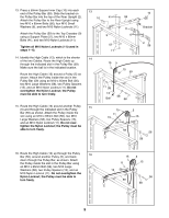
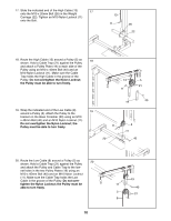
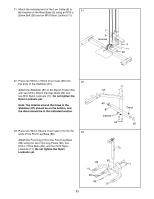
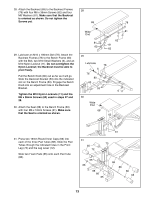
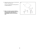
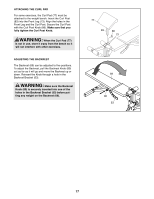
28. Attach the Backrest (69) to the Backrest Frames 28 (78) with four M6 x 36mm Screws (62) and four M6 Washers (81). Make sure that the Backrest is oriented as shown. Do not tighten the Screws yet. 69 78 29. Lubricate an M10 x 180mm Bolt (76). Attach the Backrest Frames (78) to the Bench Frame (63) with the Bolt, two M10 Small Washers (6), and an M10 Nylon Locknut (11). Do not overtighten the Nylon Locknut; the Backrest must be able to pivot freely. Pull the Bench Knob (80) out as far as it will go. Slide the Backrest Bracket (53) into the indicated slot on the Bench Frame (63). Engage the Bench Knob into an adjustment hole in the Backrest Bracket. Tighten the M10 Nylon Locknuts (11) and the M6 x 36mm Screws (62) used in steps 27 and 28. 30. Attach the Seat (68) to the Bench Frame (63) with four M6 x 16mm Screws (61). Make sure that the Seat is oriented as shown. Wide End 81 62 81 62 81 62 29 Lubricate 78 6 76 80 63 53 30 Wide End 68 63 6 11 31. Press two 19mm Round Inner Caps (66) into each of the three Pad Tubes (88). Slide the Pad Tubes through the indicated holes in the Front Leg (73) and the Leg Lever (72). Slide two Foam Pads (65) onto each Pad Tube (88). 31 65 72 61 73 65 66 88 66 65 66 88 66 65 13
-
 1
1 -
2
-
3
-
4
-
5
-
6
-
7
-
 8
8 -
 9
9 -
 10
10 -
 11
11 -
 12
12 -
 13
13 -
 14
14 -
 15
15 -
 16
16 -
 17
17 -
 18
18 -
19
-
20
-
21
-
22
-
23
 |
 |
