Weider Pro 395 B Bench English Manual - Page 9
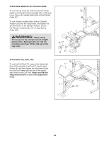
Attach the Seat Support 11 to the Seat Frame
 |
View all Weider Pro 395 B Bench manuals
Add to My Manuals
Save this manual to your list of manuals |
Page 9 highlights
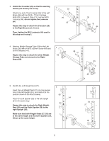
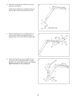
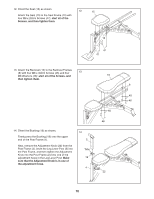
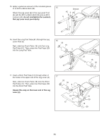
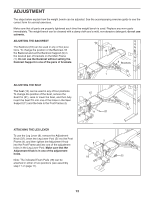
9. Using a plastic bag to keep your fingers clean, apply a small amount of the included grease to 9 an M10 x 145mm Bolt (55). Next, orient the Backrest Frames (8) as shown. Attach the Backrest Support (9) to the Backrest Frames (8) with the M10 x 145mm Bolt (55), two M10 Washers (41), and an M10 Locknut (44); do not tighten the Locknut yet. 44 41 8 Holes 41 55 Grease 9 10. Apply a small amount of the included grease to an M12 x 147mm Bolt (56). Next, slide an M12 Washer (42) onto the Bolt. With the help of a second person, align the indicated ends of the Backrest Frames (8) and the indicated end of the Seat Frame (10) with the triangular brackets on the Main Frame (1) (see the inset drawing). Next, insert the M12 x 147mm Bolt (56) through all parts, slide an M12 Washer (42) onto the Bolt, and tighten an M12 Locknut (45) onto the Bolt; do not overtighten the Locknut. Then, set the Backrest Support (9) in the desired pair of brackets on the Main Frame (1). See step 9. Tighten the M10 Locknut (44); do not overtighten the Locknut. See step 8. Tighten the M10 x 65mm Bolts (48) and the M10 Locknut (44). 10 45 42 Holes 8 9 10 42 56 4 1 Grease 11. Attach the Seat Support (11) to the Seat Frame (10) with an M12 x 87mm Bolt (52), two M12 Washers (42), and an M12 Locknut (45); do not overtighten the Locknut. See the inset drawing. Insert the Seat Pin (21) into the desired hole in the Seat Support (11) and into the hole in the Post Frame (4). 11 11 45 42 10 42 52 4 11 21 9
-
 1
1 -
2
-
3
-
 4
4 -
 5
5 -
 6
6 -
 7
7 -
 8
8 -
 9
9 -
 10
10 -
 11
11 -
 12
12 -
 13
13 -
 14
14 -
15
-
16
-
17
-
18
-
19
-
20
 |
 |
