Weider Pro 408 English Manual - Page 7
greater distance between the two lower of - bench press
 |
View all Weider Pro 408 manuals
Add to My Manuals
Save this manual to your list of manuals |
Page 7 highlights
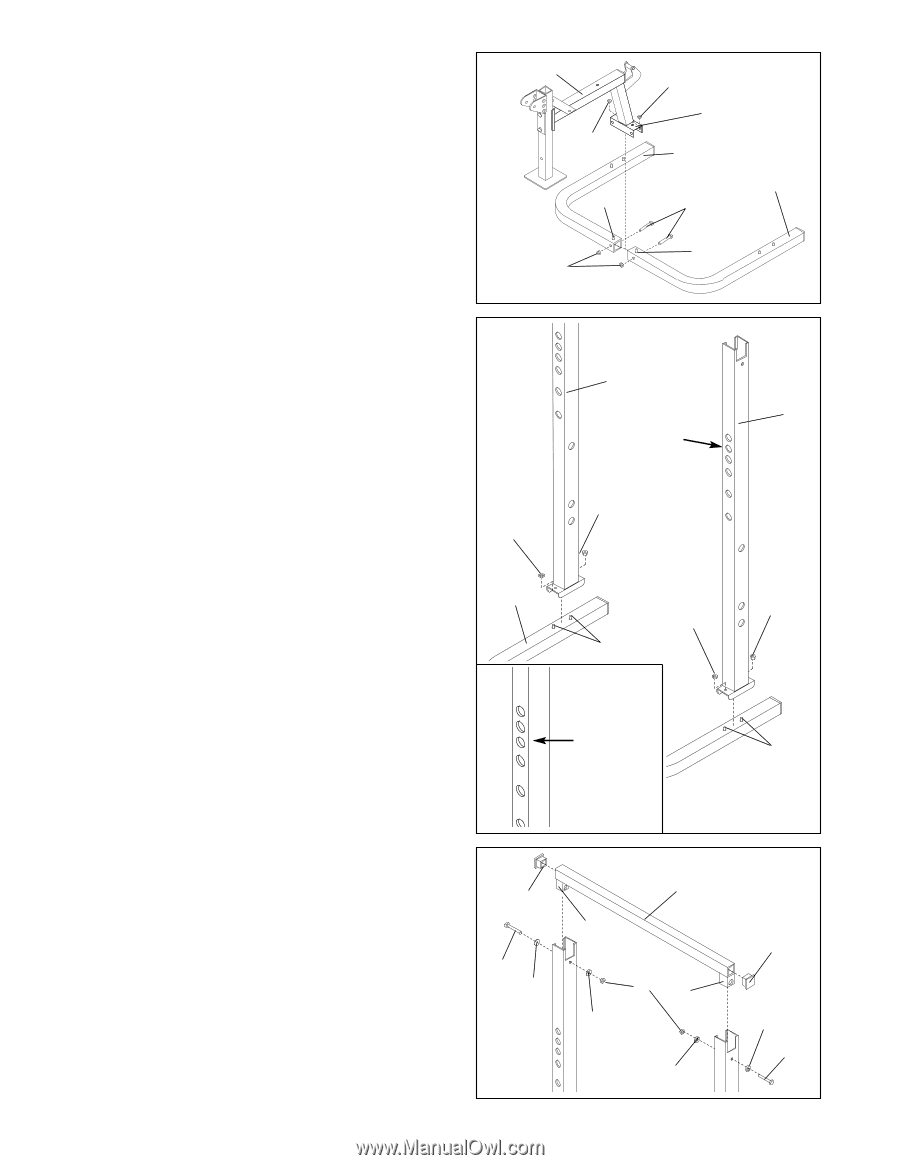
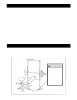
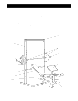
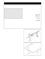
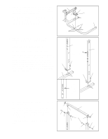
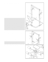
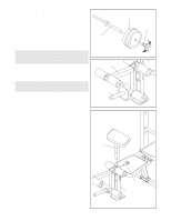
3. Slide the mounting bracket (A) on the Bench Frame 3 1 (1) onto the Carriage Bolts (30) in the Base and secure it with two M10 Nylon Locknuts (37). Do not tighten the Nylon Locknuts yet. 37 A Fasten the mounting bracket on the Frame (1) to the Right and Left Base (5, 4) with two M10 x 72mm Bolts (27) and two M10 Nylon Locknuts (37). Do not tighten the Nylon Locknuts yet. 37 4 5 30 27 30 37 4. Slide the Left Upright (6) over the Bolts (30) in the 4 Left Base (4) and secure it with two M10 Nylon Locknuts (37). Do not tighten the Nylon Locknuts yet. Mount the Right Upright (7) in the same way. Caution: Make sure both Uprights are oriented correctly. To do this, look at the upper four holes for the Weight Rests. On one side the four holes are spaced evenly, and on the other there is a greater distance between the two lower of the 37 four holes. The side with the even spacing must be facing the seat of the bench on both Uprights (see inset drawing). 4 6 7 Holes for Weight Rests 37 37 37 30 The Four Upper Holes Are 30 Evenly Spaced 5. Press a 50 x 50mm Square Cap (20) into each end of the Top Frame (8). Place the Top Frame (8) on top of the Uprights and slide the mounting brackets (B) down into the Uprights. Secure the Top Frame with two M10 x 68mm Bolts (31), four M10 Washers (38) and two M10 Nylon Locknuts (37). Tighten the Nylon Locknuts used in steps 1-5 now. 5 20 31 38 7 8 B 37 B 38 38 20 38 31
-
 1
1 -
 2
2 -
 3
3 -
 4
4 -
 5
5 -
 6
6 -
 7
7 -
 8
8 -
 9
9 -
 10
10 -
 11
11 -
 12
12 -
13
-
14
-
15
-
16
-
17
-
18
-
19
 |
 |