Weider Pro 4300 User Manual
Weider Pro 4300 Manual
 |
View all Weider Pro 4300 manuals
Add to My Manuals
Save this manual to your list of manuals |
Weider Pro 4300 manual content summary:
- Weider Pro 4300 | User Manual - Page 1
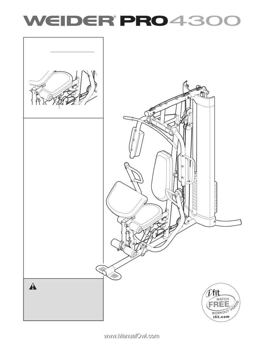
for future reference. WEIGHT SYSTEM EXERCISER Userʼs Manual Serial Number Decal (under seat) • Assembly • Adjustment • Troubleshooting • Part List and Drawing Sears, Roebuck and Co. Hoffman Estates, IL 60179 CAUTION Read all precautions and instructions in this manual before using this equipment - Weider Pro 4300 | User Manual - Page 2
PLACEMENT 2 IMPORTANT PRECAUTIONS 3 BEFORE YOU BEGIN 4 PART IDENTIFICATION CHART 5 ASSEMBLY 8 ADJUSTMENT 25 WEIGHT RESISTANCE CHART 27 CABLE DIAGRAM 28 MAINTENANCE 29 EXERCISE GUIDELINES 30 PART LIST 33 EXPLODED DRAWING 34 ORDERING REPLACEMENT PARTS Back Cover 90 DAY FULL WARRANTY Back - Weider Pro 4300 | User Manual - Page 3
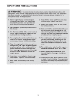
or any other type of weight to increase the resistance. 12. The weight system is designed to support a maximum user weight of 300 lbs. (136 kg). 13. Always make sure that the weight pin is inserted fully into the weight stack before exercising. 14. Over exercising may result in serious injury - Weider Pro 4300 | User Manual - Page 4
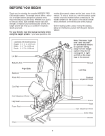
the versatile WEIDER® PRO 4300 weight system. The weight system offers a selection of weight stations designed to the front cover of this manual. Before reading further, please review the drawing below and familiarize yourself with the parts that are labeled. ASSEMBLED DIMENSIONS: Height: 6 ft. 11 - Weider Pro 4300 | User Manual - Page 5
PART IDENTIFICATION CHART Refer to the drawings below to identify small parts used in assembly. The number in parentheses by each drawing is the key number of the part, from the PART LIST in the center of this manual. Note: Some small parts may have been preattached. If a part is missing, call 1-877 - Weider Pro 4300 | User Manual - Page 6
M8 x 69mm Shoulder Bolt (87) M10 x 65mm Bolt (85) M8 x 65mm Bolt (101) M10 x 65mm Button Bolt (106) M6 x 60mm Button Screw (91) M10 x 60mm Bolt (79) M10 x 50mm Bolt (97) M10 x 45mm Bolt (86) M6 x 32mm Screw (89) M6 x 28mm Bolt (94) M8 x 75mm Carriage Bolt (83) M10 x 75mm Bolt (82) M8 x 80mm Bolt ( - Weider Pro 4300 | User Manual - Page 7
Backrest Adjustment Knob (53) Curl Adjustment Knob (58) Seat Adjustment Knob (52) 7 - Weider Pro 4300 | User Manual - Page 8
. • For help identifying small parts, use the PART IDENTIFICATION CHART on pages 5 and 6. • As you assemble the weight system, make sure all parts are oriented as shown in the drawings. • Tighten all parts as you assemble them, unless instructed to do otherwise. • Assembly requires the included hex - Weider Pro 4300 | User Manual - Page 9
1 1. Before beginning assembly, make sure that you understand the information in the box on page 8. Insert four M8 x 75mm Carriage Bolts (83) up through the Base (1). Note: It may be helpful to place a piece of tape over each Bolt head to hold it in place. 2. Orient the two Weight Guides (18) so - Weider Pro 4300 | User Manual - Page 10
6. Note: Some parts have been removed to show this step clearly. 6 Slide the two Weight Bumpers (71) onto the Weight Guides (18). Orient nine Weights (19) with the pin holes on the bottom as shown. Slide the Weights onto the Weight Guides. Insert the Weight Tube into the nine Weights (19). Make - Weider Pro 4300 | User Manual - Page 11
the Upright (2) with 7 two M8 x 80mm Bolts (100), two M8 Washers (103), and two M8 Locknuts (78). Do not tighten the Locknuts yet. Attach the Weight Guides (18) to the Top Frame (4) with two M10 x 20mm Button Screws (96) and two M10 Washers (80). 100 103 4 78 2 96 80 18 78 8. Attach - Weider Pro 4300 | User Manual - Page 12
Arm Assembly 10 10. Attach the Butterfly Frame Brace (6) to the Upright (2) with two M8 x 80mm (78). See the right inset drawing. Insert the Lock Plate Pin (95) through the Lock Plate (14) and the Leg Lever (12). Attach the tether on the Lock Plate Pin to the Front Leg (10) with an M4 x 12mm Self - Weider Pro 4300 | User Manual - Page 13
13. Apply grease to the locations shown and attach the Left Butterfly Bracket (28) to the Butterfly 13 Frame (5) with an M10 x 80mm Bolt (84) and an M10 Locknut (77). 84 Repeat this step for the Right Butterfly Bracket (29). Grease See steps 2-13. Tighten the Locknuts (77, 78, 107). 29 5 77 - Weider Pro 4300 | User Manual - Page 14
16. Orient a Press Arm Handle (17) with the 90° bend at the top as shown in the inset drawing. Attach a 16 Press Arm Handle (17) to the Right Press Arm (16) with two M10 x 65mm Button Bolts (106), four M10 Washers (80), four 11mm Spacers (99), and two M10 Locknuts (77). Repeat this step for - Weider Pro 4300 | User Manual - Page 15
19 19. See the CABLE DIAGRAMS on page 28 to identify the cables as you assemble them. Identify the Butterfly Cable (50). Grease an M8 x 22mm Shoulder Bolt (90). Attach the Cable to the Left Butterfly Bracket (28) with the Shoulder Bolt and an M8 Locknut (78). Make sure that the flat edge of - Weider Pro 4300 | User Manual - Page 16
77 23. Grease an M8 x 22mm Shoulder Bolt (90). Attach the Butterfly Cable (50) to the Right Butterfly Arm 23 (29) with the Shoulder Bolt and the flat edge of the Cable is against the Butterfly Arm. Grease 90 50 78 29 24. Identify the Lat Cable (49). Route the Cable up through the Top Frame - Weider Pro 4300 | User Manual - Page 17
25. Route the Lat Cable (49) over a Thin Pulley (24) and down through the Top Frame an M10 Locknut (77). Make sure that the Cable Trap and the Half Guards are oriented as shown. 27. Route the Lat Cable (49) up through the Top 27 Frame (4) and wrap the Cable over a Thin Pulley (24). Pull the M10 - Weider Pro 4300 | User Manual - Page 18
M12 Nut (112) all the way onto the Lat Cable (49). Thread the Lat Cable (49) into the Weight Tube (20) two turns. Tighten the M12 Nut (112) against the M12 Large Washer (98). 49 112 98 20 30. Identify the Leg Lever Cable (51). Route the Cable through the Leg Lever (12) and the Front - Weider Pro 4300 | User Manual - Page 19
), two 13mm Steel Spacers (109), and an M10 Locknut (77). Make sure that the Leg Lever Cable (51) is under the Pulley. 85 10 80 109 48 51 109 80 77 32. Route the Leg Lever Cable (51) under the 89.5mm Spacer (59), through the Upright (2), and 32 under the indicated rod - Weider Pro 4300 | User Manual - Page 20
two Half Guards (55), and an M10 Locknut (77). 35. Wrap the Leg Lever Cable (51) over a 90mm Pulley (48). Attach the Pulley to the Double "U"- 35 two Half Guards (55), and an M10 Locknut (77). 36. Wrap the Leg Lever Cable (51) under a 90mm 36 Pulley (48). Attach the Pulley to the Upright (2) - Weider Pro 4300 | User Manual - Page 21
Pulley to the Left Press Arm (15) with an M10 x 50mm Bolt (97), two Half Guards (55), an M10 Washer (80), and a Cable Trap (56). Make sure that the Cable Trap and Half Guards are oriented as shown. 21 55 2 57 47 77 80 55 51 113 97 51 15 48 55 - Weider Pro 4300 | User Manual - Page 22
40 Washer (80), a 7mm Spacer (111), and an M10 Locknut (77). Make sure that the flat edge of the Cable is against the Spacer. 2 Flat Edge 115 80 111 51 77 Seat Assembly 41 26 41. Attach the Right Butterfly Pad (35) to the Right Butterfly Arm (26) with two M6 x 60mm - Weider Pro 4300 | User Manual - Page 23
(37) into each Foam Pad (36). Repeat this step for the other Pad Tube (13) and the Leg Lever (12). Note: Lift the Leg Lever Cable (51) when inserting a Pad Tube through the hole in the bottom of the Leg Lever. 44 37 36 12 51 13 10 13 36 37 - Weider Pro 4300 | User Manual - Page 24
does not move smoothly, find and correct the problem. IMPORTANT: If the cables are not properly installed, they may be damaged when heavy weight is used. See the CABLE DIAGRAMS on page 28 of this manual for proper cable routing. If there is any slack in the cables, you will need to remove the slack - Weider Pro 4300 | User Manual - Page 25
Pin is touching the Weights, and turn the bent end upward. Note: The weight system works best when at least two Weights are used. 70 19 ATTACHING THE ACCESSORIES To attach the Lat Bar (63) to the Lat Cable (49), attach a Weight Clip (66) to the Lat Cable and the Lat Bar. Note: For some exercises - Weider Pro 4300 | User Manual - Page 26
Knob passes through a hole in the Curl Post. When you are performing exercises that do not require the Curl Pad, remove the Curl Pad (33) 32 LOCKING THE WEIGHT STACK To lock the weight stack, insert the Locking Pin (72) through one of the holes in the Guide Rods (18) and secure the Pin with the - Weider Pro 4300 | User Manual - Page 27
or the indicated hole in the Leg Lever (12). Insert the Lock Pin back through the Lock Plate. 10 14 95 12 Hole WEIGHT RESISTANCE CHART The chart below shows the approximate weight resistance at each exercise station. Weight resistance shown for the butterfly arm station is for each arm. Note: The - Weider Pro 4300 | User Manual - Page 28
The cable diagram shows the proper routing of the cables. The numbers in each drawing show the proper routing for that cable. Use the diagram to make sure that the cables and the cable traps are assembled correctly. If the cables and the cable traps are not assembled correctly, the weight system - Weider Pro 4300 | User Manual - Page 29
use solvents. TIGHTENING THE CABLES Woven cable, the type of cable used on the weight system, can stretch slightly when it is first used. If there is slack in the cables before resistance is felt, the cables should be tightened. To tighten the cables, first insert the weight pin into the center of - Weider Pro 4300 | User Manual - Page 30
motivation, keep a record of each workout. Write the date, the exercises performed, the resistance used, and the numbers of sets and repetitions completed. Record your weight and key body measurements once a month. To achieve good results, make exercise a regular and enjoyable part of your life. 30 - Weider Pro 4300 | User Manual - Page 31
copies to schedule and record your strength and aerobic workouts. Scheduling and recording your workouts will help you to make exercise a regular and enjoyable part of your life. Strength Date: Exercise 1. Lbs. Sets Reps Exercise 6. Lbs. Sets Reps 2. 7. 3. 8. 4. 9. 5. 10. Aerobic Date - Weider Pro 4300 | User Manual - Page 32
NOTES 32 - Weider Pro 4300 | User Manual - Page 33
* - Exercise Guide Cap 84 5 M10 x 80mm Bolt * - Assembly Tool 42 2 40mm x 25mm Inner 85 4 M10 x 65mm Bolt * - Grease Packet Cap 86 4 M10 x 45mm Bolt Note: Specifications are subject to change without notice. For information about ordering replacement parts, see the back cover of this manual - Weider Pro 4300 | User Manual - Page 34
EXPLODED DRAWING A-Model No. 831.14622.1 R1209A 94 114 23 114 107 102 102 114 114 94 110 104 110 21 22 49 98 112 19 20 76 19 110 104 70 71 114 102 94 107 40 99 80 114 23 80 99 77 80 99 114 102 114 94 77 55 56 48 55 18 99 17 106 80 16 77 55 8048 56 55 55 6056 48 60 97 - Weider Pro 4300 | User Manual - Page 35
EXPLODED DRAWING B-Model No. 831.14622.1 R1209A 45 45 84 24 48 80 96 74 27 109 106 109 77 74 74 90 50 46 84 80 67100 100 48 103 103 119 38 80 114 80 80 91 43 105 26 92 82 77 29 44 46 35 74 90 74 78 50 46 77 28 45 74 84 80 67 38 6780 49 84 102 67 80 67 77 77 4 - Weider Pro 4300 | User Manual - Page 36
, lawn and garden equipment, or heating and cooling systems, no matter who made it, no matter who sold it! For the replacement parts, accessories, and user's manuals that you need to do-it-yourself. For Sears professional installation of home appliances and items like garage door openers and water
-
 1
1 -
 2
2 -
 3
3 -
 4
4 -
 5
5 -
 6
6 -
 7
7 -
8
-
9
-
10
-
11
-
12
-
13
-
14
-
15
-
16
-
17
-
18
-
19
-
20
-
21
-
22
-
23
-
24
-
25
-
26
-
27
-
28
-
29
-
30
-
31
-
32
-
33
-
34
-
35
-
36
 |
 |
• Assembly
• Adjustment
• Troubleshooting
• Part List and Drawing
Model No. 831.14622.1
Serial No.
Write the serial number in the
space above for future reference.
Serial Number Decal (under seat)
WEIGHT SYSTEM EXERCISER
Userʼs Manual
CAUTION
Read all precautions and instruc-
tions in this manual before using
this equipment. Keep this manual
for future reference.
Sears, Roebuck and Co.
Hoffman Estates, IL 60179