Weider Pro 4300 User Manual - Page 22
Seat Assembly
 |
View all Weider Pro 4300 manuals
Add to My Manuals
Save this manual to your list of manuals |
Page 22 highlights
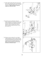
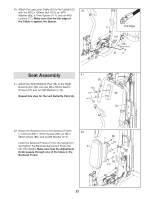
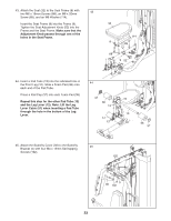
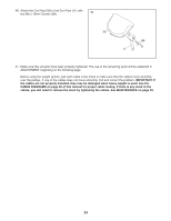
40. Attach the Leg Lever Cable (51) to the Upright (2) with the M10 x 120mm Bolt (115), an M10 40 Washer (80), a 7mm Spacer (111), and an M10 Locknut (77). Make sure that the flat edge of the Cable is against the Spacer. 2 Flat Edge 115 80 111 51 77 Seat Assembly 41 26 41. Attach the Right Butterfly Pad (35) to the Right Butterfly Arm (26) with two M6 x 60mm Button 114 Screws (91) and two M6 Washers (114). 35 Repeat this step for the Left Butterfly Pad (34). 91 34 42. Attach the Backrest (31) to the Backrest Frame (7) with two M6 x 16mm Screws (88), an M6 x 32mm Screw (89), and an M6 Washer (114). Insert the Backrest Frame (7) into the Upright (2) and tighten the Backrest Adjustment Knob (53) into the Upright. Make sure that the Adjustment Knob passes through one of the holes in the Backrest Frame. 42 31 88 7 2 53 89 114 22
-
 1
1 -
2
-
3
-
4
-
5
-
6
-
7
-
8
-
9
-
10
-
11
-
12
-
13
-
14
-
15
-
16
-
 17
17 -
 18
18 -
 19
19 -
 20
20 -
 21
21 -
 22
22 -
 23
23 -
 24
24 -
 25
25 -
 26
26 -
 27
27 -
28
-
29
-
30
-
31
-
32
-
33
-
34
-
35
-
36
 |
 |
