Weider Pro 9000 Instruction Manual - Page 5
CABLE DIAGRAMS, ASSEMBLY, Rack Assembly
 |
View all Weider Pro 9000 manuals
Add to My Manuals
Save this manual to your list of manuals |
Page 5 highlights
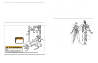
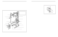
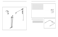
CABLE DIAGRAMS The cable diagrams below show the proper routing of the High Cable (31), the Butterfly Cable (32), and the Low Cable (33). Use the diagram to make sure that the cables and the cable traps have been assembled correctly. If the cables have not been correctly routed, the weight bench will not function properly and damage may occur. The numbers show the correct route for each cable. Make sure that the cable traps do not touch or bind the cables. Butterfly Cable (32) 4 2 5 1 3 2 Low Cable (33) 1 4 2 4 3 High Cable (31) 5 5 1 3 ASSEMBLY Make Things Easier for Yourself Everything in this manual is designed to ensure that the weight bench can be assembled successfully by anyone. However, it is important to realize that the versatile weight bench has many parts and that the assembly process will take time. Most people find that by setting aside plenty of time, assembly will go smoothly. Before beginning assembly, carefully read the following information and instructions: • Assembly requires two people. • Place all parts in a cleared area and remove the packing materials. Do not dispose of the packing materials until assembly is completed. • Tighten all parts as you assemble them, unless instructed to do otherwise. • As you assemble the weight bench, make sure all parts are oriented as shown in the drawings. • For help identifying small parts, use the PART IDENTIFICATION CHART in the centre of this manual. The following tools (not included) are required for assembly: • Two adjustable spanners • One rubber mallet • One standard screwdriver • One Phillips screwdriver • Lubricant, such as grease or petroleum jelly, and soapy water. Assembly will be more convenient if you have a socket set, a set of open-end or closed-end wrenches, or a set of ratchet spanners. Rack Assembly 1 1. Before beginning assembly, be sure that you have read and understand the information in the box above. Press a 50mm Square Inner Cap (43) into the end of the Right Base (1). Insert an M10 x 60mm Carriage Bolt (50) up through the bottom of the Right Base (1). Lay the Base on the floor. Repeat this step with the Left Base (2). 1 43 50 2 43 20 5
-
 1
1 -
 2
2 -
 3
3 -
 4
4 -
 5
5 -
 6
6 -
 7
7 -
 8
8 -
 9
9 -
 10
10 -
 11
11 -
12
-
13
-
14
 |
 |
