Weider Pro 9000 Instruction Manual - Page 9
Adjustments, Warning
 |
View all Weider Pro 9000 manuals
Add to My Manuals
Save this manual to your list of manuals |
Page 9 highlights
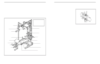
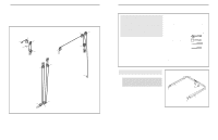
37. Attach the Curl Pad (84) to the Curl Post (83) with 37 two M6 x 16mm Bolts (80). 84 83 38. Make sure that all parts have been properly tight- 80 ened. The use of the remaining parts will be explained in ADJUSTMENTS, below. ADJUSTMENTS This section explains how to adjust the weight bench. See the EXERCISE GUIDELINES on page 22 for important information about how to get the most benefit from your exercise program. Also, refer to the accompanying exercise guide to see the correct form for each exercise. Make sure all parts are properly tightened each time you use the weight bench. Replace any worn parts immediately. The weight bench can be cleaned with a damp cloth and a mild, non-abrasive detergent. Do not use solvents. ADJUSTING THE WEIGHT RESTS AND SAFETY SPOTTERS Before beginning an exercise, move the Weight Rests (16) and the Safety Spotters (15) to sets of holes in the Uprights (3) that are best suited for that exercise. Turn the Knob (17) counterclockwise, and pull it out as far as it will go. Slide the Weight Rest or Safety Spotter to the desired height. Engage the Knob into an adjustment hole in the Upright. Turn the Knob clockwise until it is tight. The selected holes for the Safety Spotters (15) should represent the lowest point to which you want the barbell to go during the exercise. The selected holes for the Weight Rests (16) should be at a comfortable height for lifting and replacing the barbell. 16 3 15 17 Adjustment holes 16 17 3 WARNING: Always set both Weight 15 Rests (16) and both Safety Spotters (15) at the same height. 16 11. Identify the Right and Left Butterfly Arms (11, 12) by noting the positions of the welded brackets. Press two 45mm Square Inner Caps (42) into the ends of the Left Butterfly Arm (12). Wet the bottom end of the Butterfly Arm with soapy water. Slide a Large Foam Pad (18) onto the end of the Butterfly Arm. Lubricate the axles on the Top Frame (8) with grease. Orient the Left Butterfly Arm (12) as shown and slide it onto the left axle so that it is behind the bracket on the Top Frame. Have a second person secure the Butterfly Arm with two 1" Retainers (35) and a 1" Cover Cap (36). Note: Place the Retainers on top of the included retainer tool, as shown in the inset drawing. Make sure the teeth on the Retainers bend toward the tool. Gently tap the tool onto the axle. Remove the tool, and tap the Cover Cap onto the axle. Repeat this step with the Right Butterfly Arm (11). 11 Axle 35 Retainer Tool Bracket 8 11 42 35 36 Lubricate Axle Welded Bracket 12 42 18 12. Press a 25mm Round Inner Cap (45) into the 12 upper end of a Storage Tube (22), as shown. Attach the Storage Tube (22) inside the hole in the Right Base (1) with an M8 x 65mm Bolt (51), two M8 Washers (53), two 13mm x 12mm Spacers (38), and an M8 Nylon Locknut (48). Repeat this step with the other Storage Tube (not shown) and the Left Base (2). 13. Identify the Butterfly Cable (32), which has an 13 eyelet on each end. Attach one end of the Cable to the bracket on the Left Butterfly Arm (12) with an M8 x 22mm Shoulder Bolt (60) and an M8 Nylon Locknut (48). 45 22 48 53 Hole 38 1 38 53 51 2 48 32 60 12 Bracket 9
-
 1
1 -
2
-
3
-
 4
4 -
 5
5 -
 6
6 -
 7
7 -
 8
8 -
 9
9 -
 10
10 -
 11
11 -
 12
12 -
 13
13 -
 14
14
 |
 |
