Weider Pro 9000 Instruction Manual - Page 7
Warning
 |
View all Weider Pro 9000 manuals
Add to My Manuals
Save this manual to your list of manuals |
Page 7 highlights
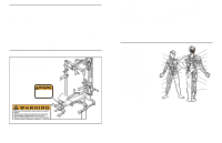
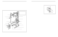
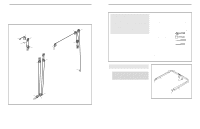
USING THE CURL PAD Remove the 50mm Square Inner Cap (43) from the Front Leg (64). Align a hole in the Curl Post (83) with the hole in the Front Leg (64). Secure the Curl Post with the Curl Knob (4). Be sure the Knob is fully tightened. Note: When not using the Curl Pad (84), store it away from the weight bench. ADJUSTING THE BACKREST The Bench Backrest (69) can be used in a decline position, a level position, or either of two incline positions. To adjust the Backrest to the decline position, remove the Bench Pin (74) and insert it through the top set of holes in the Backrest Frames (67, 68) and the Bench Frame (63). To adjust the Bench Backrest (69) to the level position, insert the Bench Pin (74) through the second set of holes from the top of the Backrest Frames (67, 68) and the Bench Frame (63). To adjust the Bench Backrest (69) to an incline position, insert the Bench Pin (74) through one of the lower two sets of holes in the Backrest Frames (67, 68) and the Bench Frame (63). WARNING: When adjusting the position of the Bench Backrest (69), make sure that the Bench Pin (74) is fully inserted through both Backrest Frames (67, 68) and the hole in the Bench Frame (63). 84 83 4 43 64 69 67 68 63 74 18 4. Attach one of the Uprights (3) to the Right Base 4 (1) with four M10 x 68mm Bolts (46), two Support Plates (14), and four M10 Nylon Locknuts (49). Do not tighten the Nylon Locknuts yet. Repeat this step with the other Upright (not shown) and the Left Base (not shown). 3 5. Press a 50mm Square Inner Cap (43) into the top 5 of the right Upright (3). Slide a Safety Spotter (15) onto the right Upright (3) and engage the Knob (17) into the lowest adjustment hole in the Upright. Turn the Knob clockwise until it is tight. Slide a Weight Rest (16) onto the right Upright (3) and engage the Knob (17) into an adjustment hole in the Upright. Turn the Knob clockwise until it is tight. Repeat this step with the left Upright (not shown). 6. Attach the Crossbar (7), with the decal on the 6 side shown, to the right Upright (3) with four M10 x 68mm Bolts (46), two Support Plates (14), and four M10 Nylon Locknuts (49). Do not tighten the Nylon Locknuts yet. Attach the Crossbar (7) to the left Upright (not shown) in the same manner. 49 49 14 1 14 46 16 17 15 43 3 Adjustment Holes 49 14 46 14 7 3 Decal 7
-
 1
1 -
 2
2 -
 3
3 -
 4
4 -
 5
5 -
 6
6 -
 7
7 -
 8
8 -
 9
9 -
 10
10 -
 11
11 -
 12
12 -
13
-
14
 |
 |
