Weider Pro 9300 English Manual - Page 7
Attach the Seat Frame 8 to the Press - assembly
 |
View all Weider Pro 9300 manuals
Add to My Manuals
Save this manual to your list of manuals |
Page 7 highlights
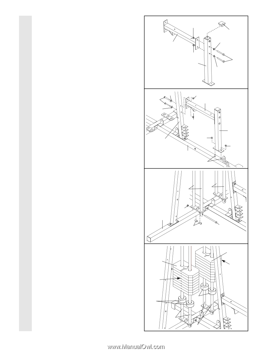
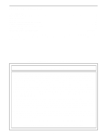
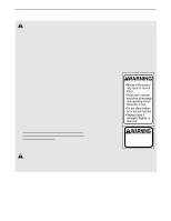
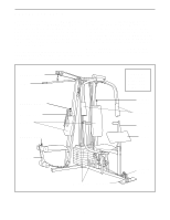
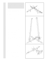
4. Insert the two 5/16" x 2 3/4" Bolts (55) 4 through the two indicated 5/16" Washers (20), and into the Curl Post (9). Slide the Seat Frame (8) onto the ends of the 5/16" x 2 3/4" Bolts (55) and secure the Seat Frame with two 5/16" Nylon Locknuts (40). Press a 2" Square Inner Cap (56) into the top of Curl Post (9). 40 8 56 20 40 55 9 20 FRAME ASSEMBLY 5. Slide the Curl Post (9) onto the indicated 5/16" x 2 1/2" Carriage Bolts (49) in the Press Base (13). Hand tighten two 5/16" Nylon Locknuts (40) onto the Carriage Bolts. Attach the Seat Frame (8) to the Press Upright (4) with two 5/16" x 2 3/4" Bolts (55), two 5/16" Washers (20), and two 5/16" Nylon Locknuts (40). Do not tighten the Nylon Locknuts yet. 6. Insert two Weight Guides (23) into one of the brackets on the Weight Base (14). Attach the lower end of the Weight Guides with a 5/16" x 6" Bolt (67), two 1/2" x 3/4" Spacers (69), and a 5/16" Nylon Locknut (40). Do not over tighten the Nylon Locknut. Attach the other Weight Guides (23) to the other bracket in the same manner. 5 20 55 20 40 8 40 9 4 40 40 13 49 6 23 23 40 14 69 67 7. Slide a Weight Bumper (27) onto each of the Weight Guides (23). Slide eight Weights (89) onto each set of Weight Guides (23). Be sure that the pin grooves are on the indicated side of each stack of Weights. 7 89 Pin Grooves 27 89 Pin Grooves 27 23 23 7
-
 1
1 -
 2
2 -
 3
3 -
 4
4 -
 5
5 -
 6
6 -
 7
7 -
 8
8 -
 9
9 -
 10
10 -
 11
11 -
 12
12 -
13
-
14
-
15
-
16
-
17
-
18
-
19
-
20
-
21
-
22
-
23
-
24
-
25
-
26
-
27
-
28
-
29
-
30
-
31
-
32
-
33
 |
 |