Weider Pro 9300 English Manual - Page 9
Arm Assembly, Frame Assembly
 |
View all Weider Pro 9300 manuals
Add to My Manuals
Save this manual to your list of manuals |
Page 9 highlights
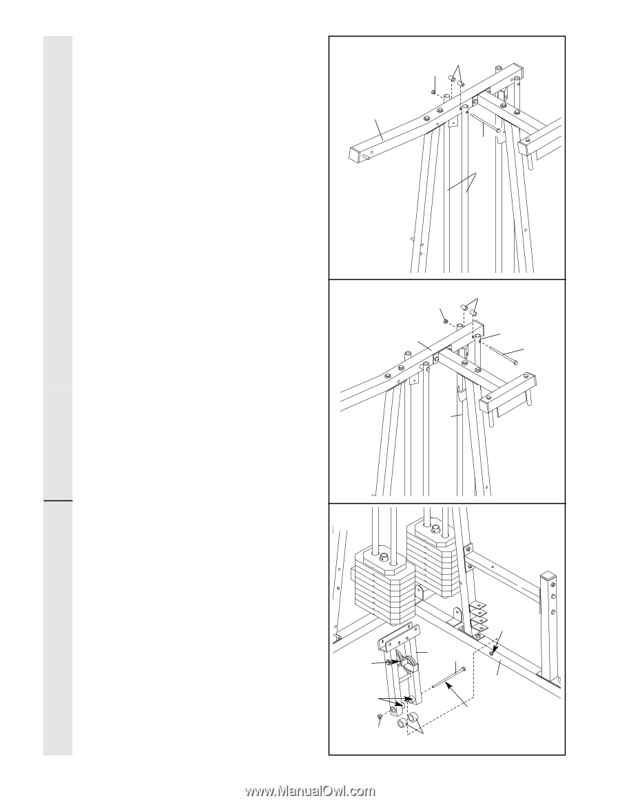
11. Attach the upper ends of one set of Weight Guides (23) to the Top Frame (2) with a 5/16" x 6" Bolt (67), two 1/2" x 3/4" Spacers (69), and a 5/16" Nylon Locknut (40). Do not over tighten the Nylon Locknut. 11 2 69 40 67 23 FRAME ASSEMBLY 12. Attach the upper ends of the other set of Weight Guides (23) to the Top Frame (2) with 12 a 5/16" x 6" Bolt (67), two 1/2" x 3/4" Spacers (69), and a 5/16" Nylon Locknut (40). Do not over tighten the Nylon Locknut. Before continuing, firmly tighten all nylon locknuts used in steps 1 through 12. 40 2 69 23 67 23 13. Locate and open the parts bag labeled "ARM ASSEMBLY." Press a 1" x 7/8" Plastic Bushing (54) onto each welded spacer on the Press Frame (12). Slide the Press Frame onto the Press Base (13) so that the Plastic Bushings are aligned with the indicated tube. Note: This will be a tight fit. Make sure that the high pulley is on the side shown. Lubricate the 3/8" x 8" Bolt (52). Attach the Press Frame (12) to the Press Base (13) with the Bolt and a 3/8" Nylon Locknut (42). 13 High Pulley Welded Spacers 42 9 12 52 Tube 13 Lubricate 54 ARM ASSEMBLY
-
 1
1 -
2
-
3
-
 4
4 -
 5
5 -
 6
6 -
 7
7 -
 8
8 -
 9
9 -
 10
10 -
 11
11 -
 12
12 -
 13
13 -
 14
14 -
15
-
16
-
17
-
18
-
19
-
20
-
21
-
22
-
23
-
24
-
25
-
26
-
27
-
28
-
29
-
30
-
31
-
32
-
33
 |
 |