Weider Pro 9635 English Manual - Page 11
Arm Assembly, Cable Assembly - parts diagram
 |
View all Weider Pro 9635 manuals
Add to My Manuals
Save this manual to your list of manuals |
Page 11 highlights
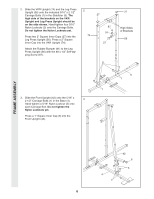
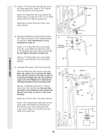
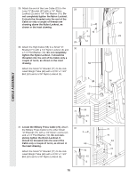
15. See the inset drawing. Attach the Military 15 Press Arm (84) to the Pivot Arm (101) with two 5/16" x 2 1/4" Bolts (33) and two 5/16" Nylon Locknuts (3). Press two 1 1/2" Square Inner Caps (32) into the indicated end of the Military Press Arm (84). Press two 1" Round Inner Caps (49) into 21 the Military Press Arm. Slide two 5" Plastic Grips (83) onto the Military Press Arm. Attach the Military Press Arm (84) to the VKR Upright (74) with a 3/8" x 3 1/4" Bolt (67) and a 3/8" Nylon Locknut (21). 74 32 49 32 84 101 83 67 56 ARM ASSEMBLY CABLE ASSEMBLY 33 101 16. Locate and open the parts bags labeled "CABLE ASSEMBLY" and "PULLEYS." 16 During steps 16 through 36, refer to the CABLE DIAGRAMS on pages 26-27 of this manual to verify proper cable routing. Before beginning this section, fully unwind the four Cables. Identify the four Cables by comparing the lengths and ends of the Cables. The approximate length of each Cable is listed (in inches) after the key number in the drawing. IMPORTANT: While assembling the cables, do not overtighten the bolts and nuts attaching the pulleys. The pulleys must be able to turn freely. 17 17. Locate the High Cable (58). Wrap the High 21 Cable around a 3 1/2" Pulley (15). Attach the Pulley to the Top Frame (55) with a 3/8" x 3 3/4" Bolt (88) and a 3/8" Nylon Locknut (21). Be sure that the end of the Cable with the ball is on the indicated side of the Pulley and that the Cable is between the Pulley and the hook. 3 55 58 88 Ball 15 Hook 84 23-79" 58-147" 72-194" 99-63" 11
-
 1
1 -
2
-
3
-
4
-
5
-
 6
6 -
 7
7 -
 8
8 -
 9
9 -
 10
10 -
 11
11 -
 12
12 -
 13
13 -
 14
14 -
 15
15 -
 16
16 -
17
-
18
-
19
-
20
-
21
-
22
-
23
-
24
-
25
-
26
-
27
-
28
-
29
-
30
-
31
-
32
-
33
 |
 |
