Weider Pro 9635 English Manual - Page 17
Insert the Bolt through the Pivot Arm 101 - pulley system
 |
View all Weider Pro 9635 manuals
Add to My Manuals
Save this manual to your list of manuals |
Page 17 highlights
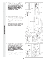
34. See inset drawing A. Attach a 3 1/2" Pulley 34 (15) and a Cable Trap (66) to the upper hole in the Long "U"-Bracket (57) with a 3/8" x 2" Bolt (12) and a 3/8" Nylon Locknut (21). Be sure that the Cable Trap is inside the Long "U"-Bracket. (Note: This may come pre- assembled.) Route the Military Press Cable (72) through the Long "U"-Bracket (57) and the 3 1/2" Pulley (15). Be sure that the Cable is in the groove of the Pulley and that the Cable and Pulley move smoothly. See inset drawing B. Slide a 5/16" Flat Washer (8) onto a 5/16" x 2 3/4 Bolt (11). Insert the Bolt through the Pivot Arm (101) from the indicated side. Tighten a 5/16" Nylon Jam Nut (93) onto the Bolt. Slide the end of the Military Press Cable (72) onto the end of the Bolt. Thread another 5/16" Nylon Jam Nut onto the Bolt. Do not fully tighten the second Jam Nut. There must be room between the two Jam Nuts for the end of the Cable to pivot. 15 57 72 21 57 11 8 15 A 66 12 B 101 93 72 CABLE ASSEMBLY 35. Locate the Leg Press Cable (99). Attach the 35 end of the Leg Press Cable to the Long "U"- Bracket (57) with a 1/4" Nylon Locknut (2) and a 1/4" Flat Washer (10). Do not completely tighten the Nylon Locknut. It should be threaded onto the end of the Cable only a couple of turns, as shown in the inset drawing. Wrap the Leg Press Cable (99) around a 3 1/2" Pulley (15). Attach the Pulley to the Leg Press Upright (56) with the 3/8" x 3 1/2" Bolt (16), a 3/8" Flat Washer (9), and a 3/8" Nylon Locknut (21). The ball on the Cable must be on the indicated side of the Pulley. Be sure that the Cable and Pulley move smoothly and that the Cable is between the Pulley and the welded rod. 2 10 57 16 15 99 17 99 Welded 2 Rod 10 57 56 Ball 9 21
-
 1
1 -
2
-
3
-
4
-
5
-
6
-
7
-
8
-
9
-
10
-
11
-
 12
12 -
 13
13 -
 14
14 -
 15
15 -
 16
16 -
 17
17 -
 18
18 -
 19
19 -
 20
20 -
 21
21 -
 22
22 -
23
-
24
-
25
-
26
-
27
-
28
-
29
-
30
-
31
-
32
-
33
 |
 |
