Weslo Boomerang 203 Uk Manual - Page 5
Be careful to avoid pinching the Wires and, Cables., Be careful to, avoid pinching, the wires and,
 |
View all Weslo Boomerang 203 manuals
Add to My Manuals
Save this manual to your list of manuals |
Page 5 highlights
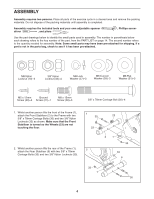
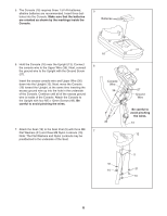
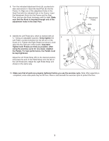
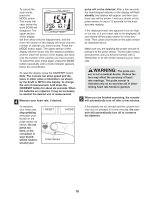
3. Whilst another person holds the Upright (13) in the position shown, connect the Upper Wire (36) to the Reed Switch Wire (43). Cut and remove the zip tie holding the Reed Switch Wire to the Frame (1). Next, connect the Resistance Cable (19) to the Lower Cable (45) in the following way: • See drawing A. Press the small cylinder on the end of the Resistance Cable (19) into the indicated hole in the connector on the Lower Cable (45). Pull the Resistance Cable up and slide it into the slot in the top of the connector. • See drawing B. Turn the Resistance Cable (19) until it is aligned with the slot in the connector, and press the Resistance Cable down into the connector. The Resistance Cable will lock into place. Carefully pull the excess Upper Wire (36) out of the top of the Upright (13), push the excess Cables (19, 45) down into the Frame (1), and insert the Upright into the Frame. Be careful to avoid pinching the Wires and Cables. Next, attach the Upright with three M8 x 15mm Screws (58), three M8 Lock Washers (57), and three M8 Curved Washers (59). 4. Slide the two slots in the Handlebar Clamp (55) onto the two indicated tabs on the Upright (13). Lift the bottom of the Handlebar Clamp away from the Upright, and insert the Handlebar (15) between the Handlebar Clamp and the Upright. Centre the Handlebar and rotate it to the desired position. Insert the Adjustment Handle (42) into the Handlebar Clamp (55) and tighten the Adjustment Handle into the Upright (13). Note: The Adjustment Handle works like a spanner. Turn the Handle clockwise, pull it away from the Upright, turn it counterclockwise, push it toward the Upright, and then turn it clockwise again. 3 Be careful to avoid pinching the wires and cables whilst inserting the Upright. 13 19 45 59 57 58 1 36 43 59 57 58 Zip Tie 59 57 58 A Connector B 19 Hole 45 4 Cylinder 19 Slot Connector Tabs 55 42 15 13 5
-
 1
1 -
 2
2 -
 3
3 -
 4
4 -
 5
5 -
 6
6 -
 7
7 -
 8
8 -
 9
9 -
 10
10 -
 11
11 -
12
-
13
-
14
-
15
-
16
 |
 |
